Propulsion

Major parts of design programs have been developed in the SVA. This includes pre-processing for propeller definition and geometry modification and recalculation processes for propellers, ducted propellers, twin and contra-rotating propellers. Furthermore, mathematically based optimisation methods and post-processing for assessment of cavitation, pressure fluctuation predictions and strength calculations using FEM analysis, and interfaces for 3D modeling are included. All of these programs are contained within the program package of VORTEX. Other propeller manufacturers and classification societies use, among other things, this software for design and certification. The continuous development of design tools is supported through close contact with these propeller manufacturers and classification societies.
The SVA has had, among other things, significant contributions to the development of the twin propeller concept from SCHOTTEL and set milestones in the development of low-noise propellers for research, naval vessels and submarines. For large tug boats, ducted propellers are designed with more than 200 t thrust. In the development of ducted propellers with high static thrust demands in particular, the broad experience with extensive CFD calculations of propulsion systems on the ship can be made use of.
Designs of propellers and propulsion systems can be fully tested in the SVA in model scale, whereupon despite advanced calculation methods, model testing cannot be dispensed with. After propulsion or cavitation testing, the propeller design can be improved to meet the highest standards of practice.
To determine the behaviour of ship and propulsion system and the tuning of the engine, trial runs are accompanied by the SVA during which special full-scale measurements (power measurement, vibration, pressure fluctuations and acoustics measurements, cavitation observations, manoeuvring measurements) are conducted.
Context Related References / Research Projects
[1] Schulze, R.: Globale Optimierung von Propellern, STG-Sprechtag, Flensburg 14. März 1997
[2] Schulze, R.; Bertolo, G.; Brighenti, A.; Kaul, S.: LUITO Development and Optimisation of the Propulsion System; Study, Design and Tests
PRADS, The Hague, September 20 – 25, 1998, 1998 Elsevier Science B.V.
[3] Schulze, R.: Globale Optimierung von Propellern und Propulsionssystemen, Schiff & Hafen 3/2005
[4] Mertes, P., Heinke, H.-J.: Aspects of the Design Procedure for Propellers Providing Maximum Bollard Pull, ITS 2008, Singapore, May 2008
[5] Steinwand, M.; Grabert, R.; Schulze, R.: Ruderentwurf – Aktuelle Entwicklungen, 102. STG Jahreshauptversammlung, Berlin, 23. Nov. 2007
[6] Schulze, R.; Richter, H.: Redundante Antriebe für Einschraubenschiffe, 102. STG Jahreshauptversammlung, Berlin, 23. Nov. 2007
[7] Schulze, R., Weber, A.: Application of the new FORTJES&rmark; Z-drive from REINTJES on planning vessels; 11th Intern. Conference on Fast Sea Transportation, FAST 2011, Honolulu, Hawaii, USA, Sept. 2011
[8] Schulze, R., Weber, A.: The new FORTJES&rmark; Z-drive from REINTJES with cotra rotating propellers for high speed applications, 11th Intern. Conference on Fast Sea Transportation, FAST 2011, Honolulu, Hawaii, USA, Sept. 2011
[9] Heinke, H.-J., Lübke, L. O.: Maßnahmen zur Energieeinsparung, Schiff & Hafen 10/2014
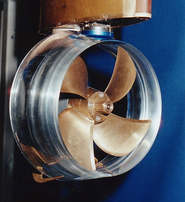
The accelerating nozzle causes an increase in flow velocity and hence a discharge of the propeller. Ducted propellers with an acceleration nozzle are used for highly loaded propellers and propellers with restricted diameters.
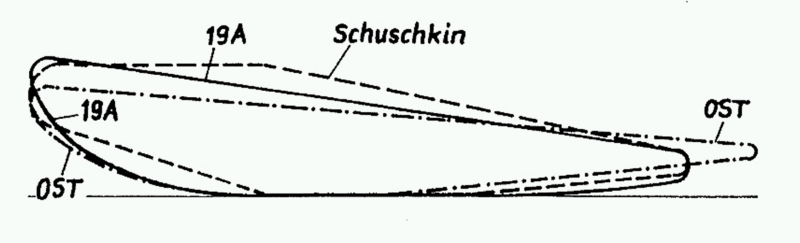
Since its foundation in 1953, the SVA Potsdam has been working on the development and optimisation of ducted propellers for inland and fishing vessels as well as tugs as well as thrusters. In addition to conventional ducted propellers (Wageningen, Schuschkin, OST), unconventional, partially integrated nozzle and controllable pitch propellers have been studied extensively in particular.
Based on a series of tests in the context of an R & D project with a combination of propellers of the Wageningen B-series and OST nozzles, polynomial coefficients were developed for ducted propeller systems with OST nozzles [10]. At lower thrust loads, the OST nozzle profile increases the mass flow through the propeller disc and causes a jet expansion at the nozzle outlet. The characteristics of ducted propellers with OST nozzles can be calculated with polynomial coefficients and used for propulsions prediction.
In the field of CFD calculation, research projects were conducted in close cooperation with ANSYS Germany GmbH for ducted propeller calculation. Based on the developed methods, systematic numerical calculations of ducted propellers were implemented in the R & D project “Correlating Z-Drives with Nozzles” to develop a method for Reynolds number correction (conversion of model test results to the full-size version).
The continued development and validation of the bollard pull and propulsion prediction for tugs with large power capacity has been the subject of R & D projects and industry projects. In the R & D projects “Increasing the Design Safety of Ducted Propeller Systems at Bollard Pull Conditions” and “Reynolds Number Effects on Bollard Pull Predictions” [5], [6] the influences of cavitation and scale on the bollard pull of tugs with ducted propellers were presented in detail. With these results, the risk of thrust break down of ducted propeller can be found in the design stage.
In the R & D project “Forecasting Reliability for the Power Requirement of Tugs with Ducted Propeller Systems”, GeoSim tests and calculations were carried out for tugs at the point of propulsion. The results of these studies have been incorporated into the propulsion forecasting methods for ships with ducted propellers.


Context Related References / Research Projects
[1] Abdel-Maksoud, M.: Convergence Study of Viscous Flow Computations Around a High Loaded Nozzle Propeller, Numerical Towing Tank Symposium NuTTS 2000, Tjärnö, Sweden, September 2000
[2] Abdel-Maksoud, M., Heinke, H.-J.: Scale Effects on Ducted Propellers, 24th Symposium on Naval Hydrodynamics, Fukuoka, Japan, July 2002
[3] Gutsche, F.: Düsenpropeller in Theorie und Experiment, Jahrbuch der STG, Bd.53, 1959
[4] Heinke, H.-J., Philipp, O.: Development of a skew blade shape for ducted controllable pitch propeller systems”, Proceedings, PROPCAV’95, Newcastle, 1995
[5] Heinke, H.-J., Hellwig, K.: Aspekte der Pfahlzugprognose für Schlepper großer Leistung, 104. Hauptversammlung der STG, Hamburg, November 2009
[6] Mertes, P., Heinke, H.-J.: Aspects of the Design Procedure for Propellers Providing Maximum Bollard Pull, ITS 2008, Singapore, May 2008
[7] Philipp, O., Heinke, H.-J., Müller, E.: Die Düsenform – ein relevanter Parameter der Effizienz von Düsen-Propeller-Systemen, STG-Sprechtag „Hydrodynamik schneller Schiffe und ummantelter Propeller“, Berlin, Potsdam, September 1993
[8] Philipp, O., Heinke, H.-J., Binek, H.: Contribution of Hydrodynamics for the Calculation of Ducted Units for Ships at Shallow Water, HYDRONAV’ 95, Gdansk, November 1995
[9] Schroeder, G.: Wirkungsgrad von Düsenpropellern mit unterschiedlicher Düsen- und Propellerform, Schiffbautechnik 17 (1967) 8
[10] Schulze, R., Manke, H.: Propellersysteme mit Ostdüsen, HANSA, 137 (2000) 2
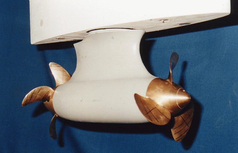
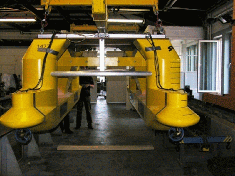
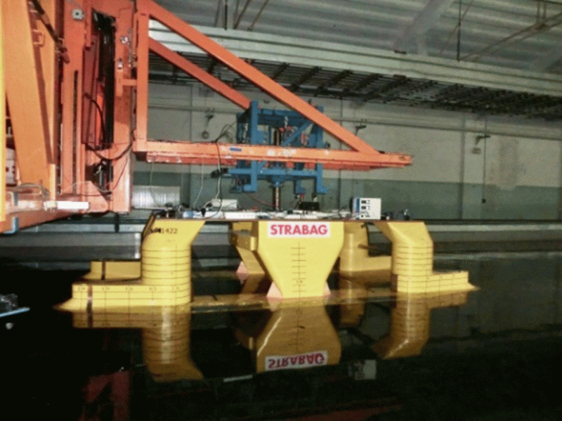
Twin propellers
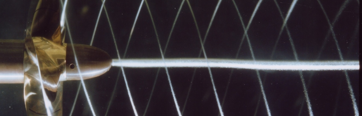
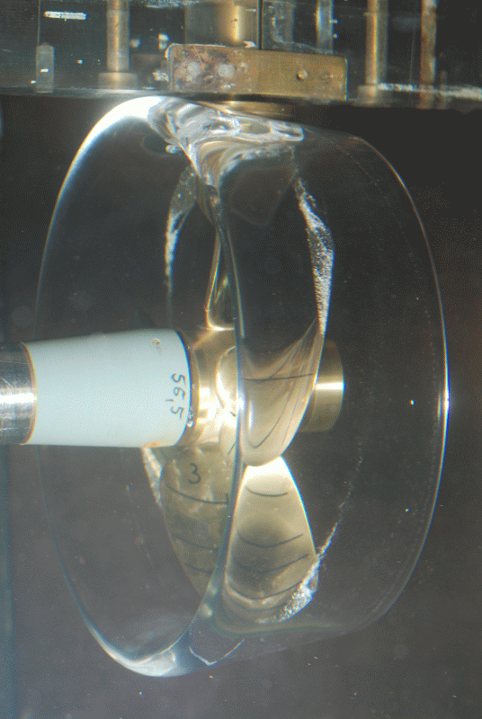
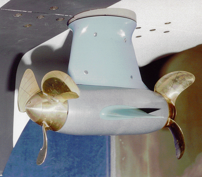
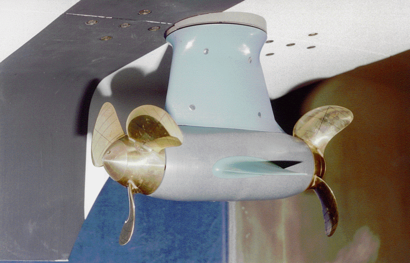
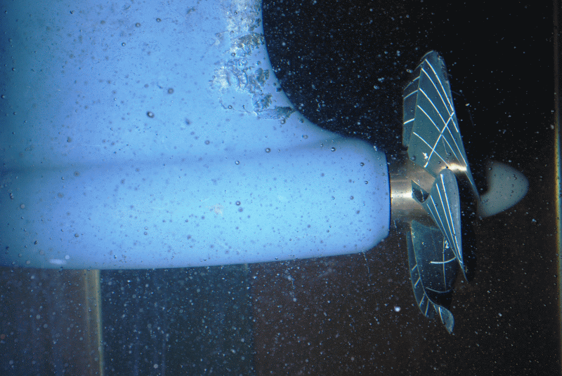
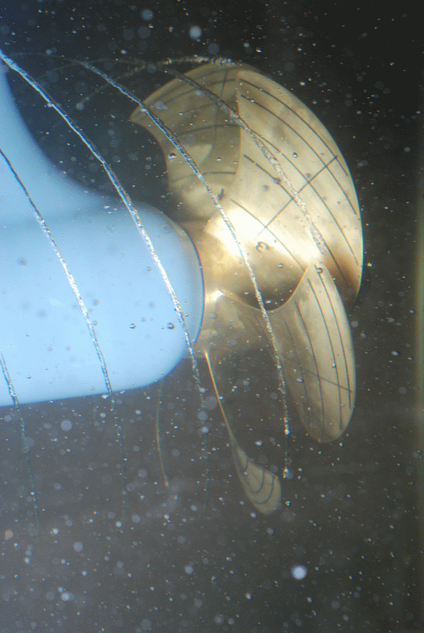
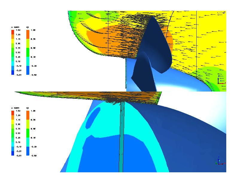
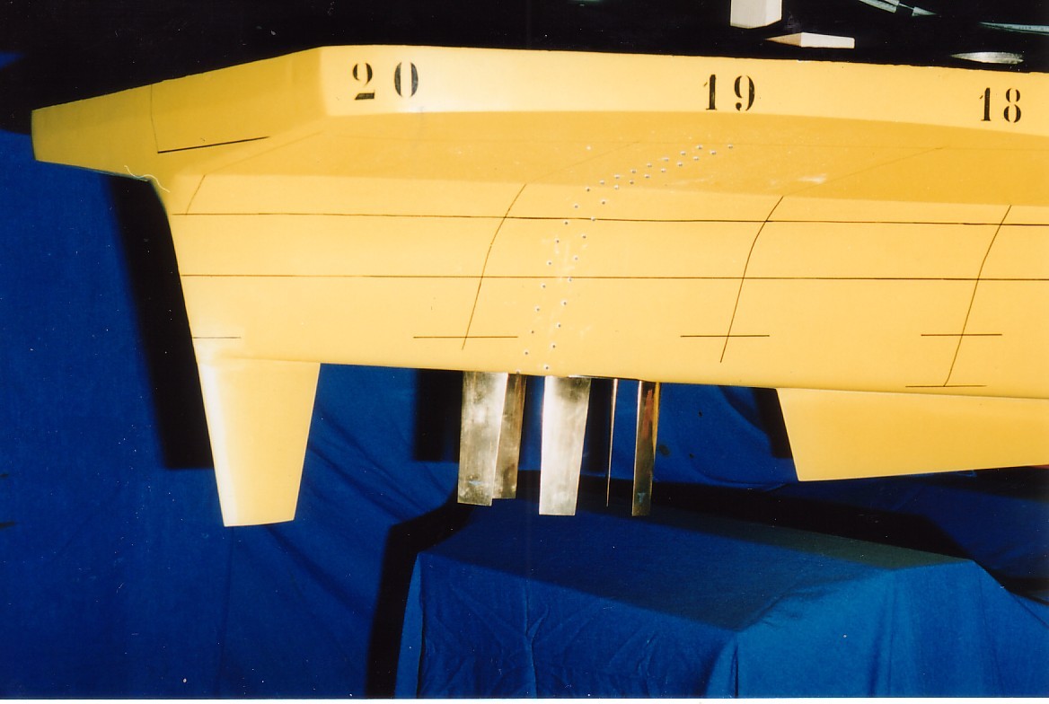
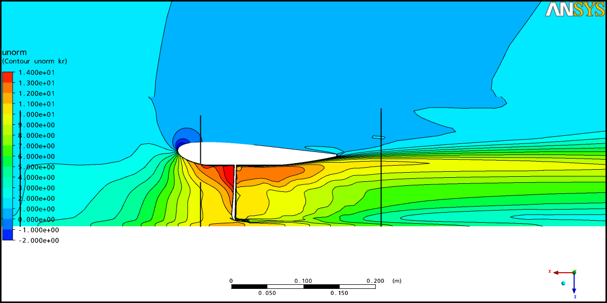
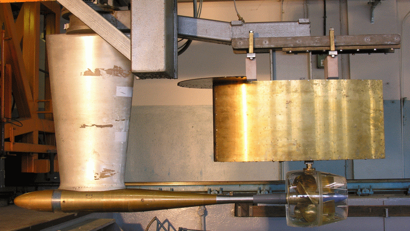
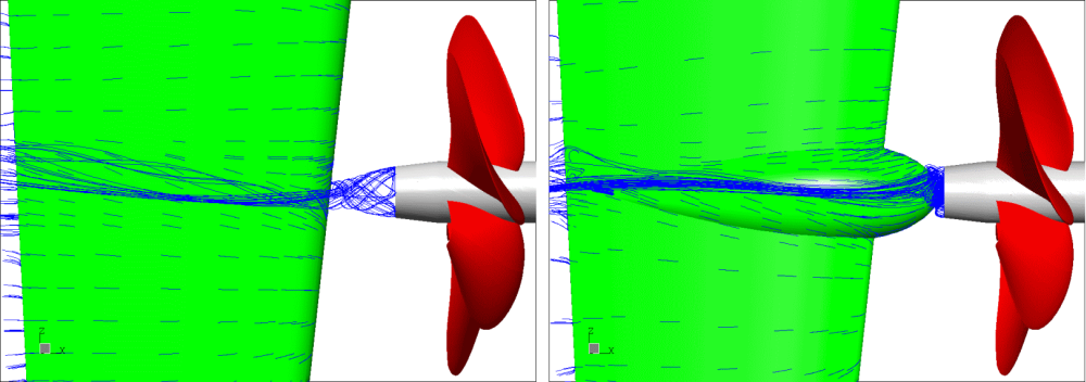
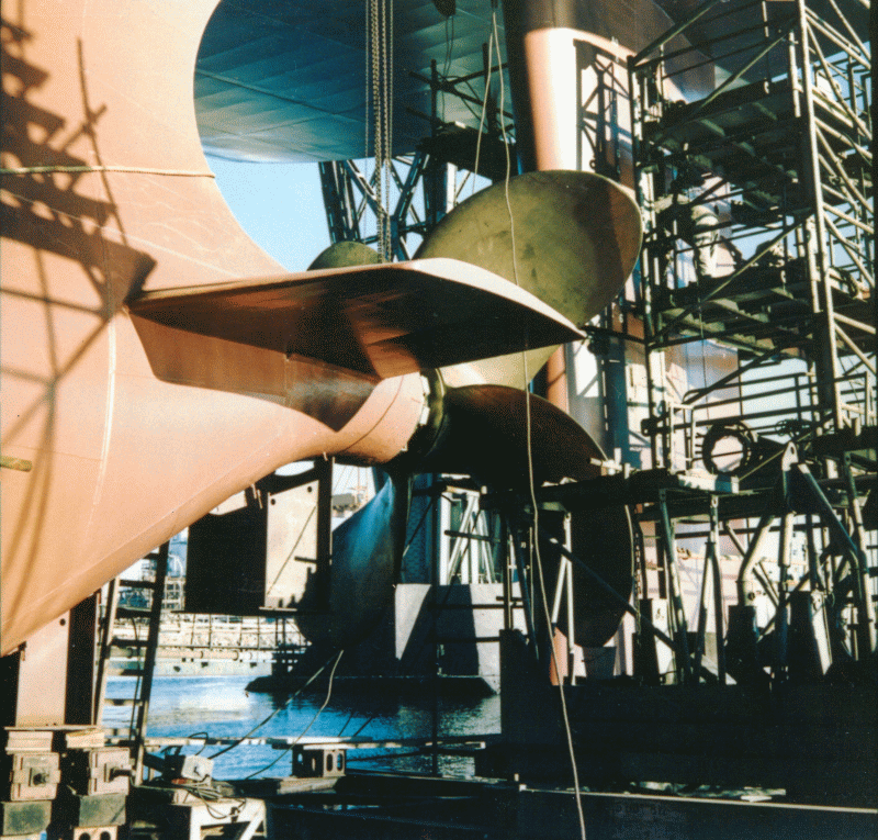
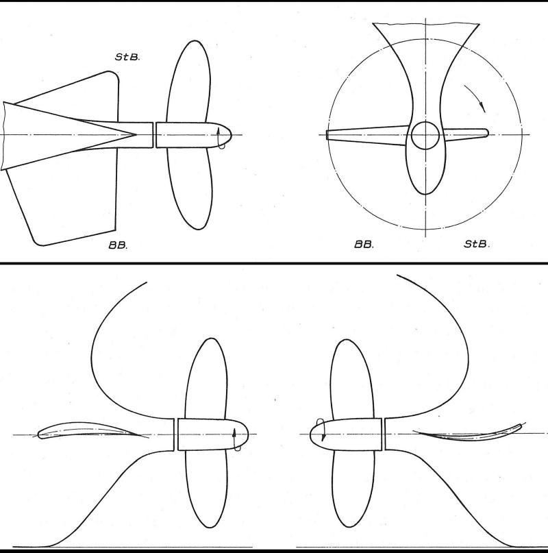
Twin propellers work with a pull and a push propeller with the same rotational direction. The design of the rear propeller places increased demands on the calculation method. Twin propellers should be arranged such that the vortex of the pulling front propeller passes between the wings of the rear pushing propeller. By the contraction of the propeller wash of the pulling propeller, additional water from the sides reaches the pushing propeller.
If twin propellers are used on thusters (Schottel Twin Propeller (STP)), or Podded Drives (Siemens Schottel propulsor (SSP)), the housing must be hydrodynamically optimised and provided with guide fins. The twist in the propeller wash of the pulling propeller is partially recovered in this way and influences the inflow to the targeted pushing propeller.
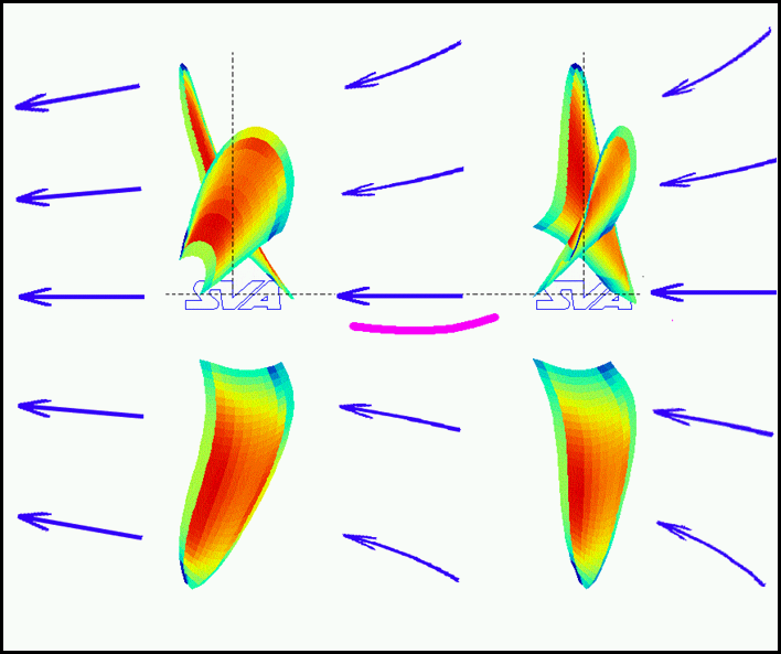
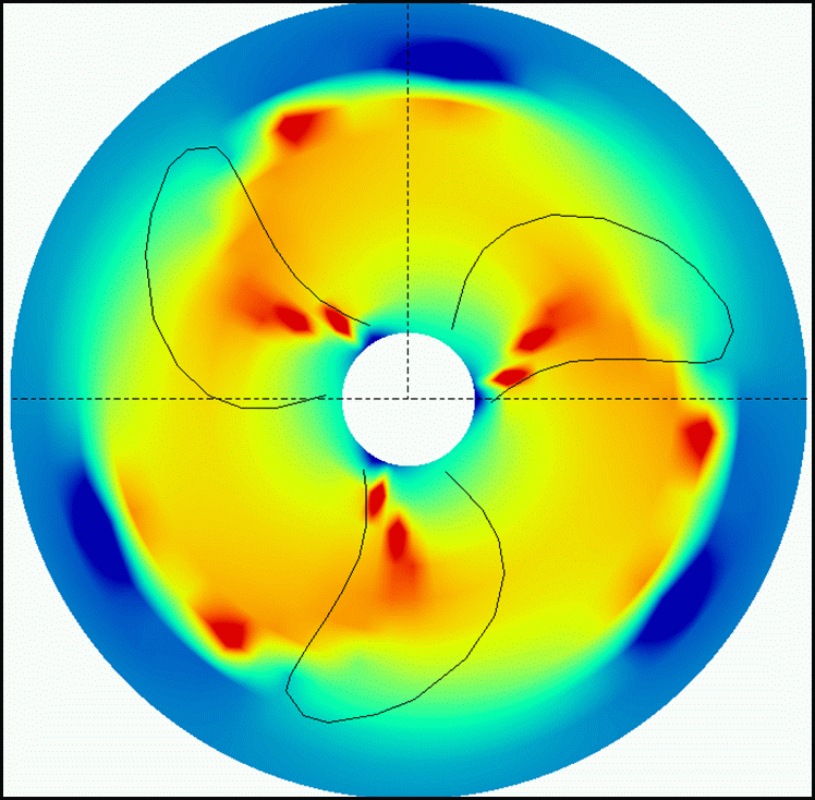
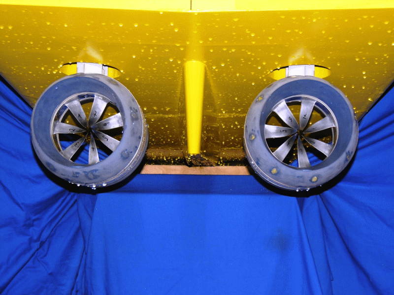
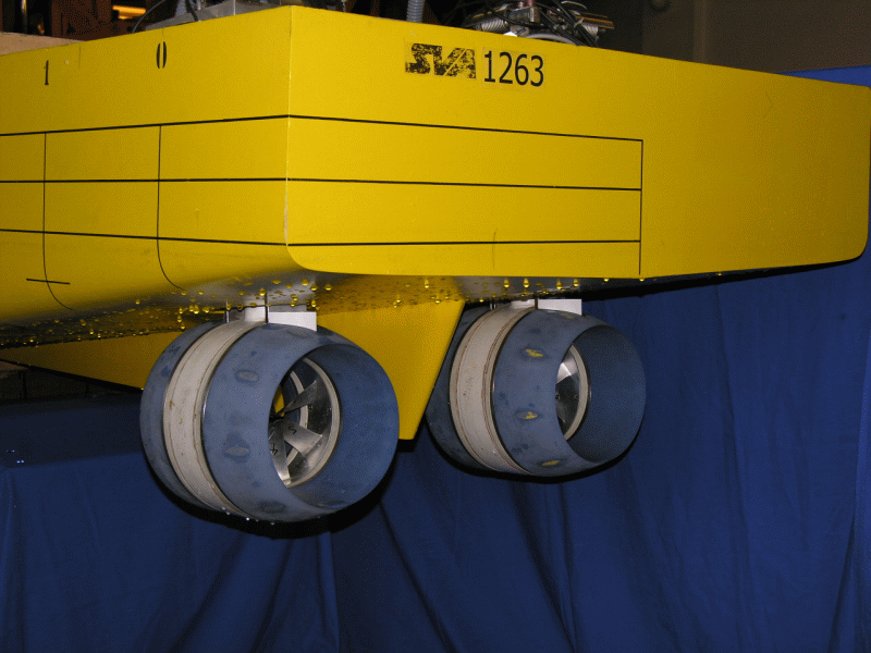
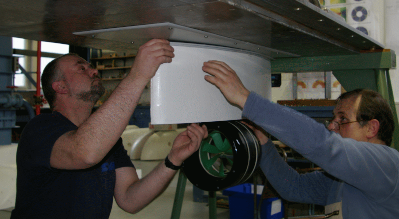
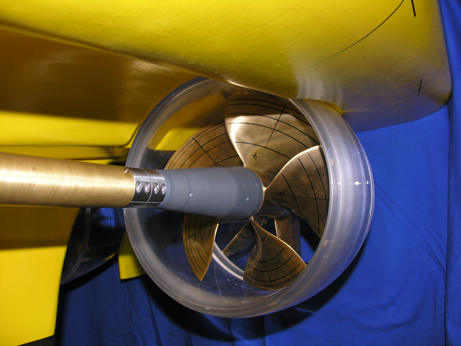
The SVA‘s VORTEX propeller calculation method has been adapted for the design and optimisation of twin propellers [1]. The following photos show examples of the hydrodynamic model and the calculated inflow to a pushing propeller.
Contra-rotating Propeller
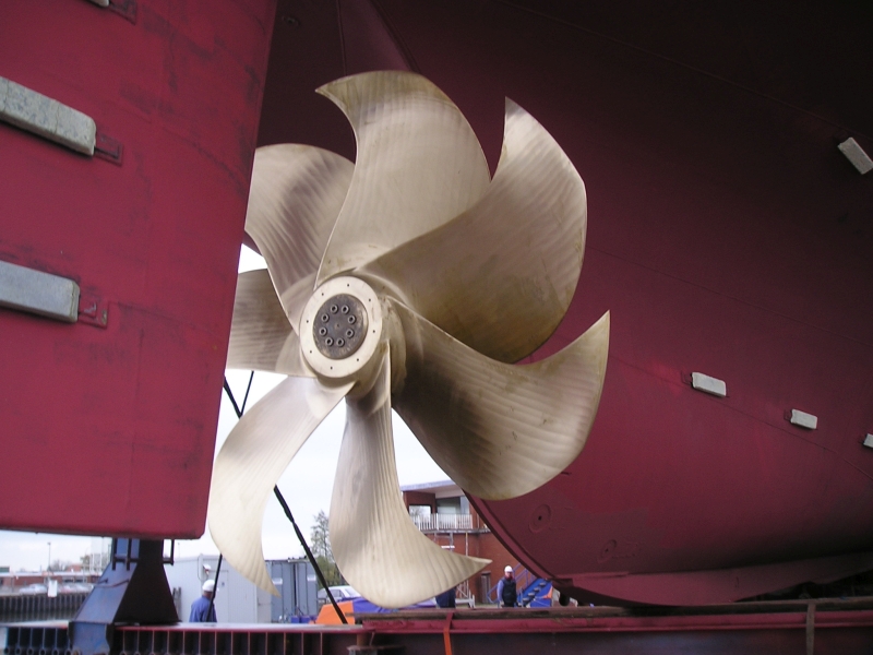
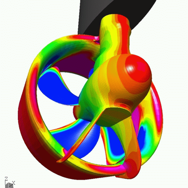
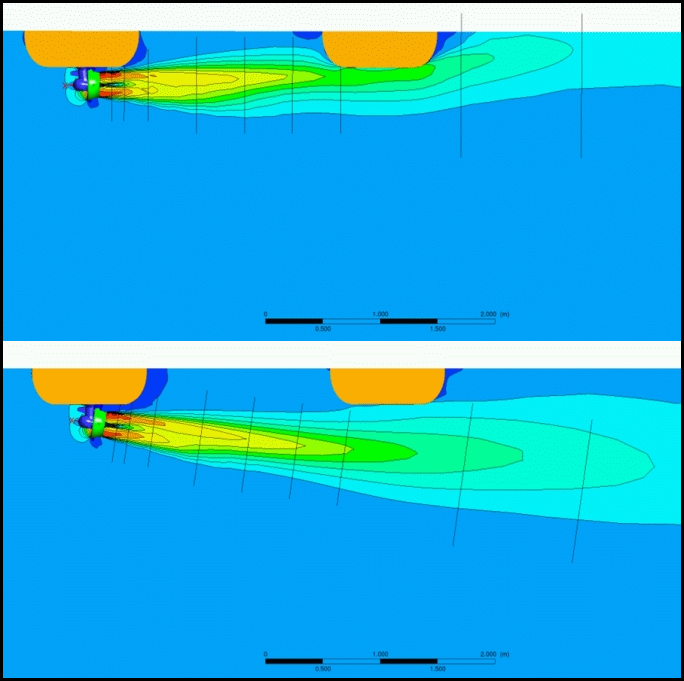
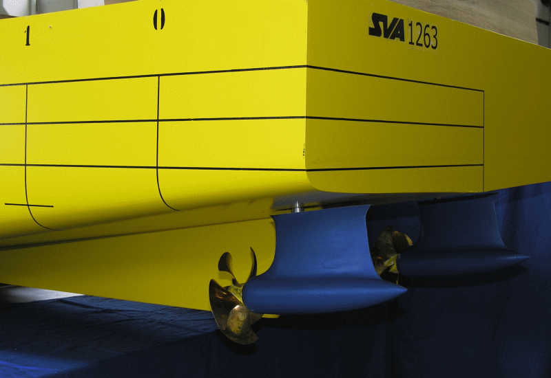
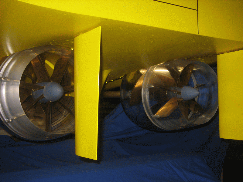
Contra-rotating propellers consist of two contra-rotating propellers. Through the reverse rotating propeller, rotational losses can be avoided because the rear propeller can use the rotational energy of the flow which is induced by the forward propeller. In addition, the load is distributed over the two propellers.
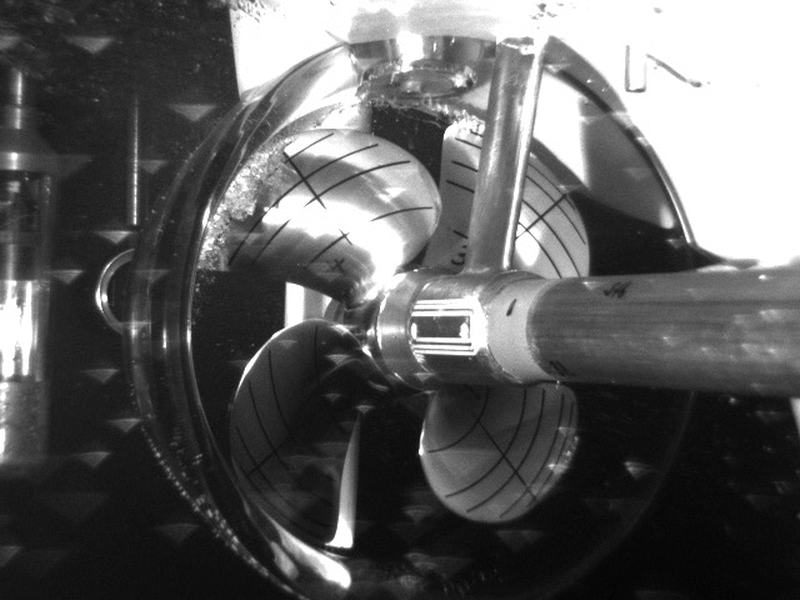
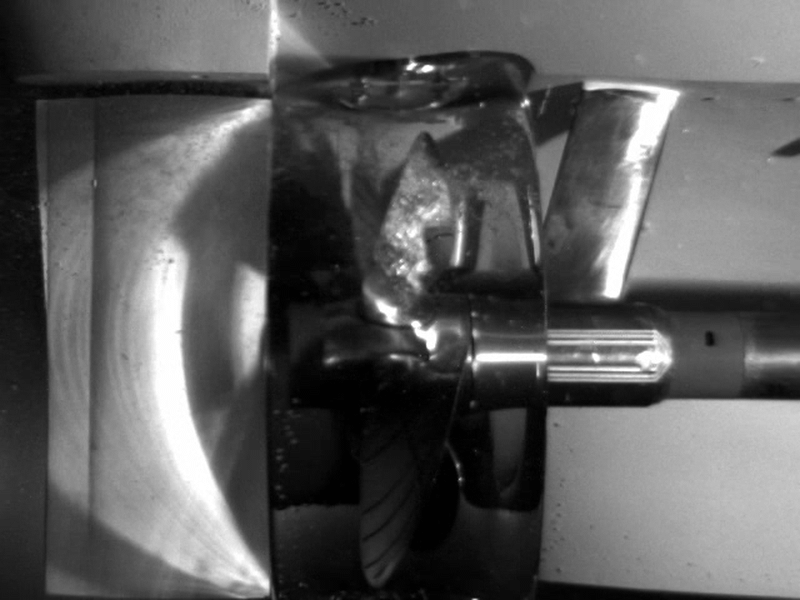
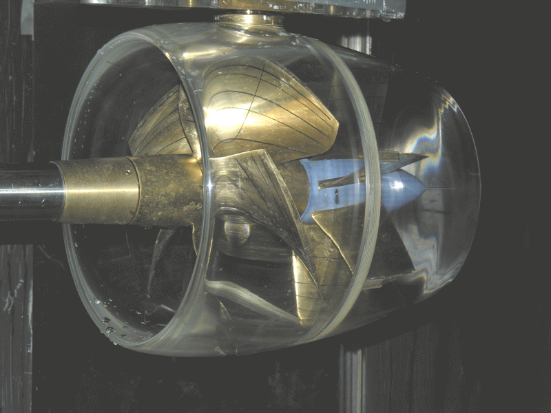
The SVA has measuring systems for the study of contra-rotating propeller systems in both the towing tank and cavitation tunnel. In recent years systematic studies of the effect on efficiency of the distance between the contra-rotating propellers and the layout of pods between the contra-running propellers have been carried out.
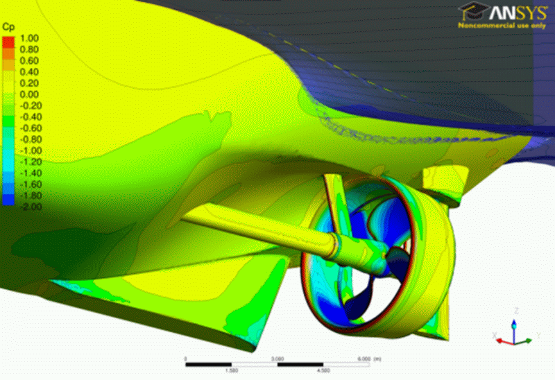
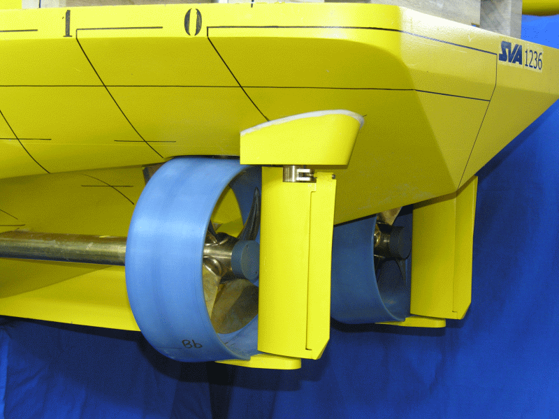
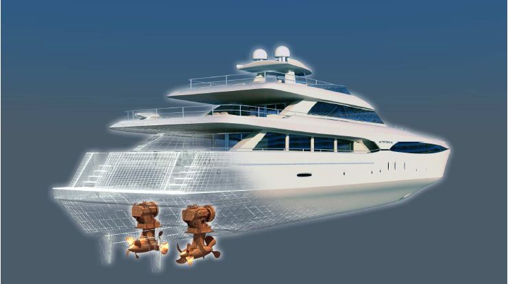
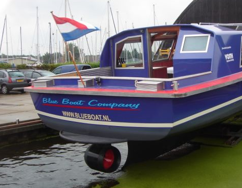
On behalf of REINTJES, the Fortjes® pod propulsion system was developed [5], [6]. The propulsion system is used especially in planing and semi-planing yachts up to 40 m long and in a power range of up to 3000 kW. The SVA’s VORTEX method was and is used for the design of contra-rotating propellers. Gondola and shaft were completely newly designed to optimally take advantage of the contra-rotating propeller and the pod.


Context Related References / Research Projects
[1] Schulze, R.; Bertolo, G.; Brighenti, A.; Kaul, S.: LUITO Development and Optimisation of the Propulsion System; Study, Design and Tests, PRADS, The Hague, September 20 – 25, 1998
[2] Kaul, S.; Heinke, H.-J.; Abdel Maksoud, M.: Hydrodynamische Optimierung von Podded Drives und aktuelle Anwendungen in der Großausführung (Anwendungsbeispiele SSP), 54. Sitzung des FA „Schiffshydrodynamik“ der STG, Hamburg, 13.09.2000
[3] Edel, K.-O.: Zum Entwurf gegenläufiger Propeller nach der Theorie von Lerbs (77. Mitteilung der SVA), Schiffbauforschung 10 (1971) 5/6
[4] Schmidt, D.: Propulsionsuntersuchungen mit Einzelpropeller und Gegenlaufpropeller am Modell eines Containerschiffes, Schiffbauforschung 14 1/2/1975
[5] Schulze, R.; Weber, A.: Application of the new FORTJES® Z-drive from REINTJES on planing vessels, 11th Intern. Conference on Fast Sea Transportation, FAST 2011, Honolulu, Hawaii, USA, Sept. 2011
[6] Schulze, R.; Weber, A.: The new FORTJES® Z-drive from REINTJES with contra rotating propellers for high speed applications, 11th Intern. Conference on Fast Sea Transportation, FAST 2011, Honolulu, Hawaii, USA, Sept. 2011
Special propulsion and measuring systems have been developed for the study of thrusters. The SVA owns propulsion and measuring systems for use in the towing tank and cavitation tunnel for testing thrusters with pushing or pulling propellers, twin and also contra rotating propellers. The systems allow the measurement of thrusts and moments of the propellers and the determination of housing resistance. The system forces and torques of the thruster are measured with 3- or 6-component balances.
Tests and calculations for thrusters are carried out in particular for propeller manufacturers (determination of the characteristics of thrusters, optimisation and development), shipyards and shipping companies (Propulsion). To convert the model test results to full-scale, the SVA has developed its own method for Reynolds number correction for thrusters. Systematic CFD calculations of thrusters were carried out in the R & D project “Correlation of Z-Drives with Ducted Propellers” [2], [4].
In recent years, aspects of DPability of thrusters were increasingly analysed. As part of the research project “Thruster for Dynamic Positioning” [5], [6] extensive studies on the influence of gondola and nozzle angle on the operating parameters of the thruster, the interaction of the thruster with the platform, and the mutual interaction of the thrusters were performed.
For the study of DP capability of platforms, special propulsion and measuring systems have been developed to ensure the variability of the inclination of the gondola housing and an unlimited pivoting of the thruster.
Context Related References / Research Themes
[1] Abdel-Maksoud, M., Heinke, H.-J.: Investigation of Viscous Flow around Modern Propulsion Systems, CFD’99, Ulsteinvik, Norway, June 1999
[2] Abdel-Maksoud, M., Heinke, H.-J.: Scale Effects on Ducted Propellers, 24th Symposium on Naval Hydrodynamics, Fukuoka, Japan, July 2002
[3] Heinke, H.-J.: Azimuthing propulsion – Experiences of SVA, 6. SVA – Forum „Azimuthing Propulsion – new challenges and chances“, Potsdam, April 1998, Schiffbauforschung 38 (1999) 1
[4] Heinke, H.-J., Abdel-Maksoud, M., Pierzynski, M. (2006): Korrelation Z-Antrieb mit Düsenpropeller, Schiff & Hafen, 2006, Heft 5
[5] Heinke, H.-J.: Model Tests with the Voith Radial Propeller, 3rd Hydrodynamic Symposium on Voith Schneider Propulsion, Heidenheim, June 2010
[6] Heinke, C.: Erhöhung der DP-Fähigkeit durch optimalen Einsatz von Thrustern, STG-Hauptversammlung, Hamburg, November 2012, Jahrbuch der Schiffbautechnischen Gesellschaft, 107. Band, 2012
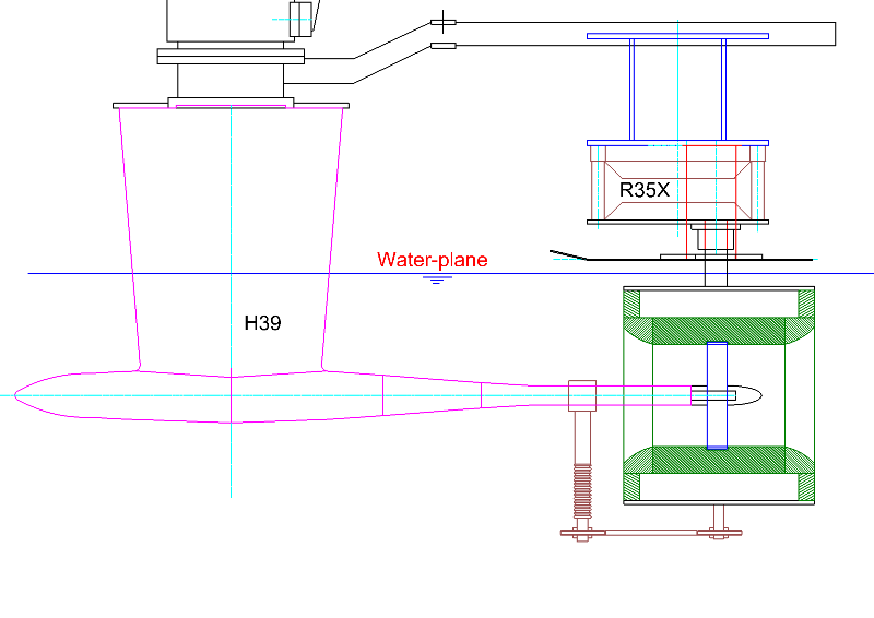
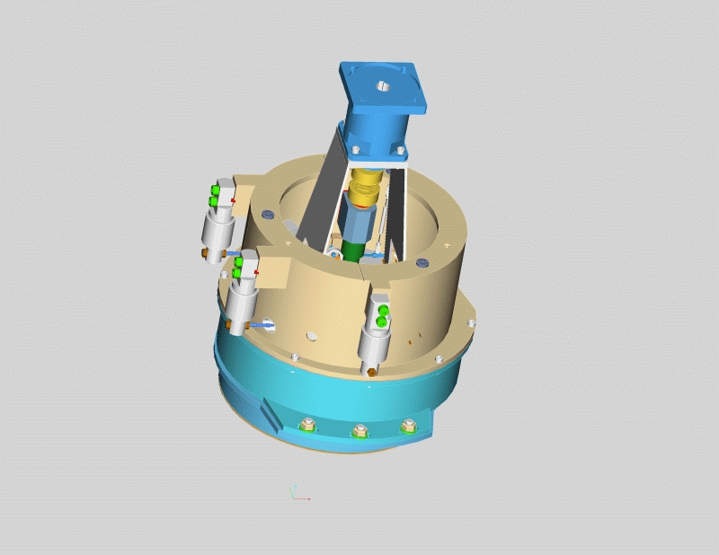
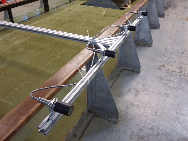
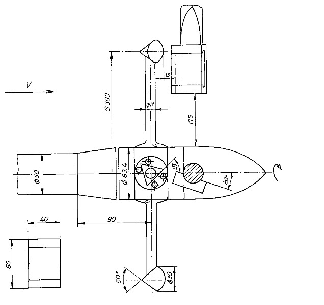
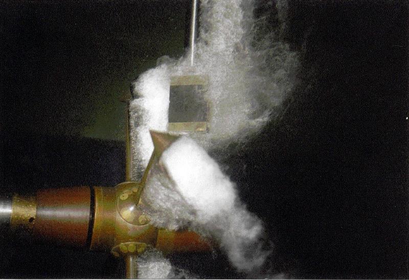
Thrusters of various designs are used to improve manoeuverability. The variations go from impeller, z-drives and retractable types to permanently installed channel thrusters. For the design of bow thrusters, details are needed on the basic parameters of the propeller and interaction with the channel in particular. For bow thrusters with propellers, different approximation methods were derived. At SVA, the method of Bladt and Wagner [3] is used for the design of thrusters. Investigations with thrusters can similarly be carried out as ducted propellers up to a certain size (relation of propeller diameter to length of the tunnel). The following figure shows a schematic diagram of the experimental setup.
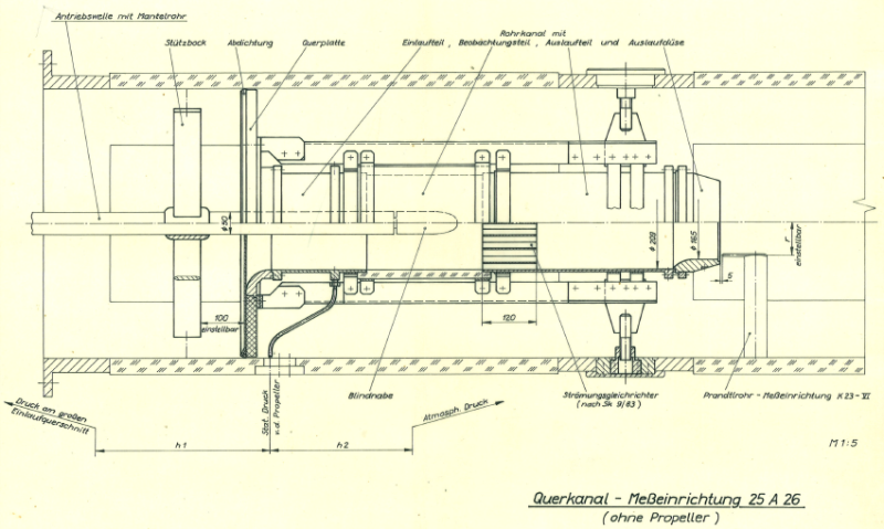
For cavitation tests with propellers for thrusters, the cross-channel system 25A26 was developed [2].
The propeller is driven with the J25 dynamometer. The channel inner diameter is 209 mm. At the end of the channel a nozzle-like constriction is arranged. This nozzle causes a throttling effect that achieves high thrust loads of the propeller in the experiments without a working impeller. Smaller loads can be realised by increasing the velocity in the pipe by a working impeller. The velocity in the channel is determined by pressure measurements. The velocity measuring device is calibrated by the measurement of the velocity distribution in the jet of the outlet of the nozzle. Therefor the LDV-measuring device is used in the cavitation tunnel. The calibration is performed with and without propellers. The static pressure which is required for calculating the cavitation number is measured in the entrance of the channel. The entrance of the cross channel can be equipped with a vertical or inclined plate relative to the channel axis.
Context Related References / Research Projects
[1] Vollheim, R.: Modellversuche zur Entwicklung eines Bugstrahlruders Schiffbauforschung 18 1/2/1979
[2] Schröder, G.: Eine Einrichtung für Modellversuche an Propellern für Querstrahlruder Schiffbauforschung 23 3, 1984
[3] Bladt, K.-J.: Beitrag zur Auslegung von Querschubanlagen mit Propeller für Schiffe, www.jbladt.drupalgardens.com, 2013
The podded drive is a propulsion system comprised of the components propellers and pod housing. The development and optimisation of podded drives requires knowledge of the interaction between propeller and pod housing and about the influence of design parameters on the characteristics of the system.
SVA Potsdam has been working in the field of podded drives since 1995 [1], [2]. Among other studies, the applicability of podded drives, dynamic flow calculations, analyses of various podded drives as well as numerous model studies have been performed there [3], [4], [8]. Developments for podded drives were conducted in collaboration with various manufacturers [3], [9].
As part of a BMWi funded project “Integrated Ship Design for Ships with Podded Propulsion Systems”, aspects of ship design for ships with podded drives were examined. In the BMWi funded project “High-Speed Pod”, concepts for podded drives with application speeds up to 30 knots were developed and studied experimentally and computationally [5], [6]. The ideas and findings resulting from these projects were the basis for the development of High Efficiency Pods with HTS technology [9].
The manoeuvrability of propulsion systems with podded drives were examined as part of a BMBF funded project [7]. The arrangement of the pod at the stern of the ship, the use of fins, and the influence of the propeller assembly were analysed experimentally and computationally.
Standard podded drives with pull and push propeller variants have been developed and investigated experimentally [6], [8], [9]. The pod housings (gondolas) were particularly varied with regard to the gondola diameter and the transition from the propeller to the gondola in order to determine the influence of geometric parameters on the characteristics of podded drives (open water, propulsion, cavitation).
The development and the study of podded drives places high demands on measurement technology and experimental methods. For open water, propulsion and cavitation measurements, manoeuvring and speed measurement systems on podded drives have been developed, tested and used successfully. To validate the evaluation and forecasting methods for measurements with podded drives, CFD calculations were performed.
With the available azimuth measuring systems for podded drives, pull, push, twin, and counter-rotating propeller assemblies can be analysed. Among other things, the thrusts and moments of the propeller are measured in the shaft and the lateral and vertical forces can be measured at the housing.

Context Related References / Research Projects
[1] Heinke, H.-J.: Azimuthing propulsion – Experiences of SVA, 6th SVA-Forum “Azimuthing Propulsion – new challenges and chances”, Potsdam, 29th April 1998
[2] Abdel-Maksoud, M., Heinke, H.-J.: Investigation of Viscous Flow Around Modern Propulsion Systems, CFD ’99, The International CFD Conference, 5-7 June 1999, Ulsteinvik
[3] Kaul, S., Heinke, H.-J.; Abdel-Maksoud, M.: Hydrodynamische Optimierung von Podded Drives und aktuelle Anwendungen in der Großausführung, 54. Sitzung des FA „Schiffshydrodynamik“ der STG, Hamburg, September 2000
[4] Heinke, H.-J.: Kavitationsuntersuchungen zu Podded Drives, 20. Strömungstechnische Tagung des Instituts für Strömungsmechanik der TU Dresden, 6. Oktober 2000
[5] Heinke, H.-J.: Alternative Propulsion Concepts for Fast Navy Ships, Part II: Podded drives for navy ships, International Lecture Day “Unconventional Hull Forms for Naval Vessels”, Potsdam, September 2001
[6] Heinke, C., Heinke, H.-J.: Investigations about the Use of Podded Drives for Fast Ships, FAST 2003, Ischia (Italy), Oct. 2003
[7] Steinwand, M.: Manoeuvrability of a Single Screw Ship with Pod, Hydronav’2003, Gdansk, Poland, Oct. 2003
[8] Heinke, H.-J.: Investigations about the forces and moments at podded drives, First International Conference on Technological Advances in Podded Propulsion, Newcastle, UK, April 2004
[9] Heinke, H.-J.: Hydrodynamische Untersuchungen für einen Podded Drive mit HTS-Synchronmaschine, Statustagung Schifffahrt und Meerestechnik, Bundesministerium für Wirtschaft und Technologie, 3. Dezember 2009, Rostock-WaPartner
In the project “Offshore Support Vessels with Voith Schneider Propellers” basic investigations were performed for the propulsion of OSV’s with VSP’s [6]. The focus was again on the interaction between VSP and hull. Simultaneously, the current methods of evaluation have been reviewed.
For model testing, VSP models are provided by the Voith company. For normal power and speed prediction, the thrust measurement on VSP’s is not absolutely necessary. However, the additional amount of preparation and testing time lends itself to optimisation questions.
Context Related References / Research Projects
[1] Heinke, H.-J.: Model tests with Voith Schneider Propellers at high thrust coefficients, Hydrodynamic Symposium – Voith Schneider Propulsion, Heidenheim, März 2006
[2] Heinke, H.-J.: High-Speed Camera Observations of the Cavitation at a Voith Schneider Propeller, 2nd Symposium Voith Schneider Technology, Heidenheim, June 2008
[2] Jürgens, D.; Grabert, R.: New Hydrodynamic Aspects of Double Ended Ferries with Voith-Schneider Propeller, 2nd International Conference on Double Ended Ferries, Alesund, Norway, 2003
[4] Grabert, R.: New Insight into the Hydrodynamics of Double-Ended Ferries with Voith Schneider Propellers, 3rd Hydrodynamic Symposium on Voith Schneider Propulsion, Constance, 16 – 18 June 2010
[5] Grabert, R.: Analysis of the Interaction VSP – Hull of Modern OSV, 4th Hydrodynamic Symposium on Voith Schneider Propulsion, Heidenheim, 12 – 14 June 2012
[6] Heinke, C.: Investigations of OSV with VSP Propulsors at SVA Potsdam, 5th Hydrodynamic Symposium on Voith Schneider Propulsion , Heidenheim, 30.9. – 2.10. 2014
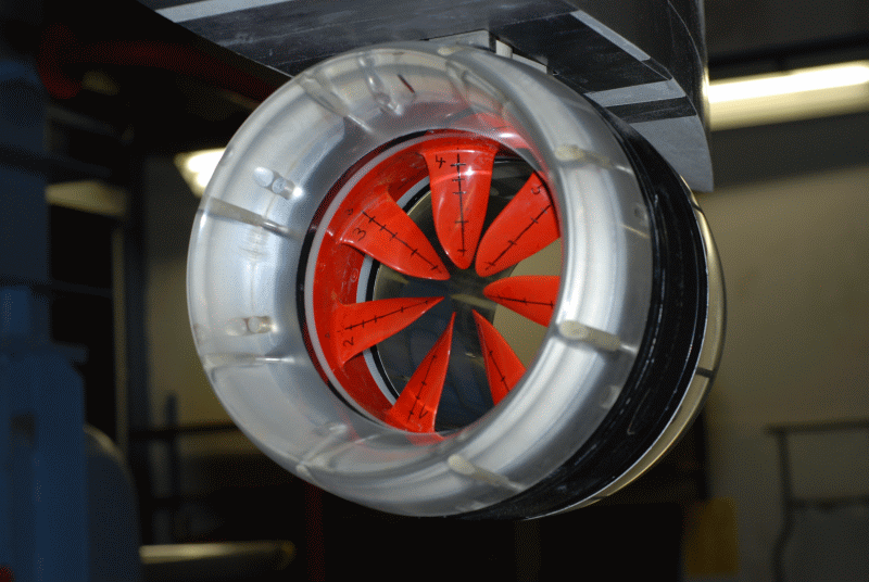
The forces and moments on the different elements of the inline thrusters were calculated in the model and at full-scale. The results of these calculations were the basis for the investigation of the Reynolds number effects and for the optimisation of the rotor and nozzle geometry.
Propulsion and maneuvering tests showed the applicability of inline thrusters for main propulsion system of ships [1], [2].
Context Related References / Research Projects
[1] Heinke, C.: Flachwassergeeignete Propulsionssysteme mit hoher Effizienz, SVA-Bericht 3502, FuE-Abschlussbericht, Potsdam, November 2008
[2] Heinke, H.-J.: Inline Thruster als Hauptantriebssystem, SVA-Bericht 3670, FuE-Abschlussbericht, Potsdam, Mai 2010
The linear jet is located underneath the ship’s hull. Basic research in the R & D project “Development of Linear Jets for Yachts” [1] showed that the deep submerged water jet is a propulsion system with high efficiency and good cavitation characteristics and can be used, in particular, for fast ships and ships with draught restrictions. During the period from 2000-2005, studies and projects were conducted at the SVA for ships with deep submerged waterjets in collaboration with the industry and manufacturers of waterjets. At the end of 2005, Voith Turbo Schneider Propulsion GmbH & Co. KG [4] (VOITH) took over the development and production of the DWJs renaming them Voith Linear Jets (VLJ). Together with Voith, the R & D project “Development and Optimisation of Deeply Submerged Waterjets” (2006 – 2007) and “Propulsion of Ships with Deeply Submerged Waterjets” (2008 – 2010) were carried out in the SVA [2], [4]. The main goals were the optimisation of the submerged water jets, the determination of the open water characteristics and cavitation characteristics of DWJs, the hydrodynamic integration of DWJs in ship design, the development of the experimental methodology and predicting methods as well as identification of the propulsion characteristics of ships with DWJs. In 2012 VOITH received the first order for a twin set of Voith Linear jets (VLJ) from the British company Turbine Transfer Ltd. for a Wind Farm Support Vessel (WSV). In 2013 the VLJs were developed and manufactured by VOITH. At SVA, systematic experiments [3] and CFD calculations were performed referencing the full-scale measurements from the WSV to check the prediction methods.

Context Related References / Research Projects
[1] Bohm, M., Jürgens, D.: LINEAR-Jet: A propulsion system for fast ships, PRADS 1998, The Hague, The Netherlands
[2] Heinke, H.-J., Hellwig; K.: Tiefgetauchter Waterjet – Entwicklungsstand und Ausblick, Marineforum 12/2005
[3] Heinke, H.-J.: Latest Hydrodynamic Results of the Voith Linear Jet, 5th Symposium on Voith Schneider Technology 2014, Heidenheim
[4] Jürgens, D., Heinke, H.-J.: Untersuchung tiefgetauchter Waterjets, STG-Hauptversammlung, Hamburg, Jahrbuch der Schiffbautechnischen Gesellschaft, 100. Band, 2006
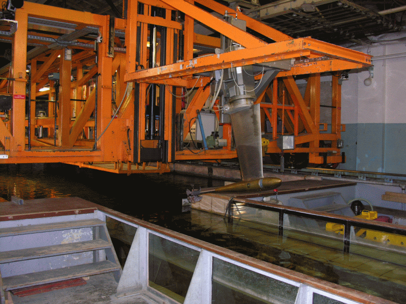
In open water tests the characteristics of the propeller are measured in homogeneous inflow. Open water tests are mostly performed in the towing tank. For this purpose, the SVA utilises open water carriages and propeller dynamometers. In open water carriage FK1 Kempf & Remmers, the integrated inner dynamometer can be used with different measuring ranges to measure with the highest possible accuracy. In addition, the open water carriage can be used to measure forces and moments on the individual blades of the propeller. For this purpose, measuring hubs have been developed for propellers with three, four and five blades. For the investigation of counter rotating propellers, the dynamometer R40 Kempf & Remmers is used. The dynamometer is installed in the open water carriage FK4 and can be driven by one or two motors to examine the counter rotating propellers with fixed or variable speed ratios. Most open water tests are carried out with the dynamometers H29 and H39 from Kempf & Remmers. The dynamometers differ in size and range and are appropriately selected to match the model propeller.
The characteristics of the propeller can also be determined in the cavitation tunnel K15A. The influence of the limited size of the cross section on the flow velocity or the thrust and torque of the propeller is considered in the test evaluation. The SVA uses the method of Glauert [1] to calculate the wall correction. The cavitation tunnel K15A is equipped with the dynamometers J25 and H36 from Kempf & Remmers. The dynamometer H36 can be used to measure the forces and moments on the individual blades of the propeller by means of a measuring hub.
All dynamometers can be combined with single and three-component balances. Thus, the measurement of the open water characteristics of jet propellers or complex propulsion systems is possible. In addition, two dynamometers and balances can be used together to test counter rotating propellers, tandem propellers or other special propulsion systems.
The shaft inclination of dynamometer H29, H39 and H36 can be varied. The dynamometer H39 and H36 can also be equipped with devices for the measurement of transverse and vertical forces of the propeller.
The detailed description of the experimental procedures and evaluation is contained in the documentation of the Potsdam Propeller Test Case (PPTC) [2].
Context Related References / Research Projects
[1] Glauert, H.: Wind Tunnel Interference. W. F. Durand, Aerodynamic Theory, Vol. IV, Berlin 1935, Division L: Airplane Propellers; 296 – 306
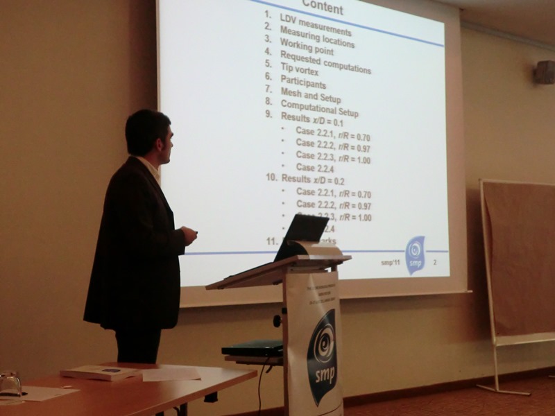
[2] smp’11: 2nd Symposium on Marine Propulsors & 1st Workshop on Cavitation and Propeller Performance, June 17 -18, 2011, Hamburg, Germany

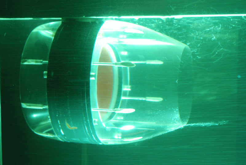
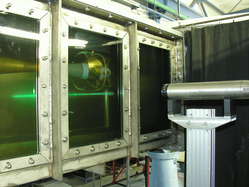
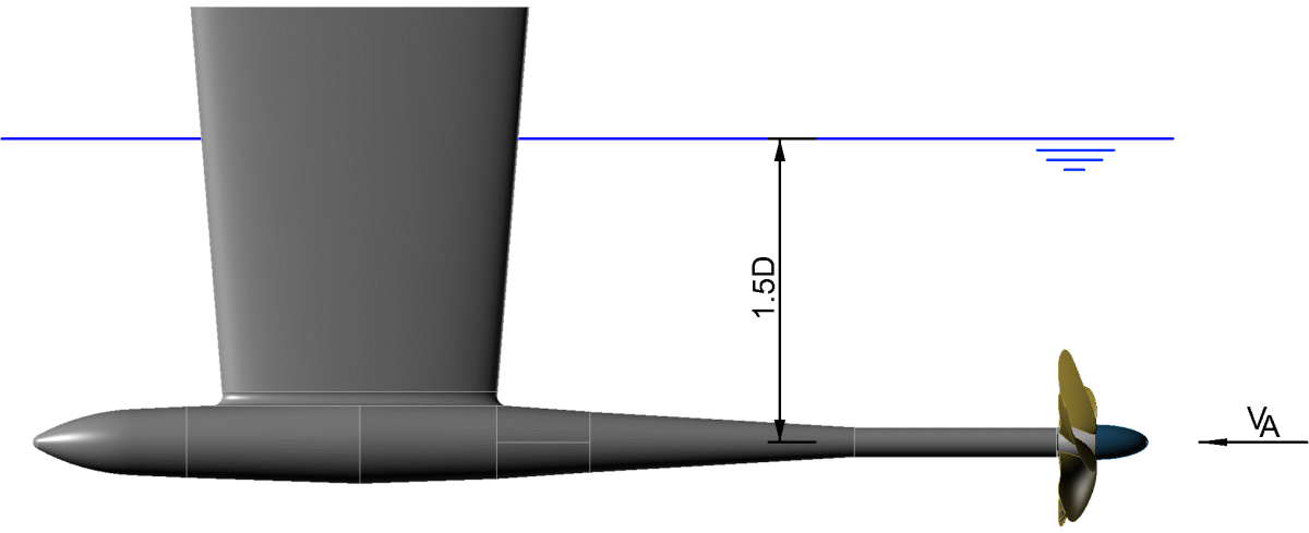
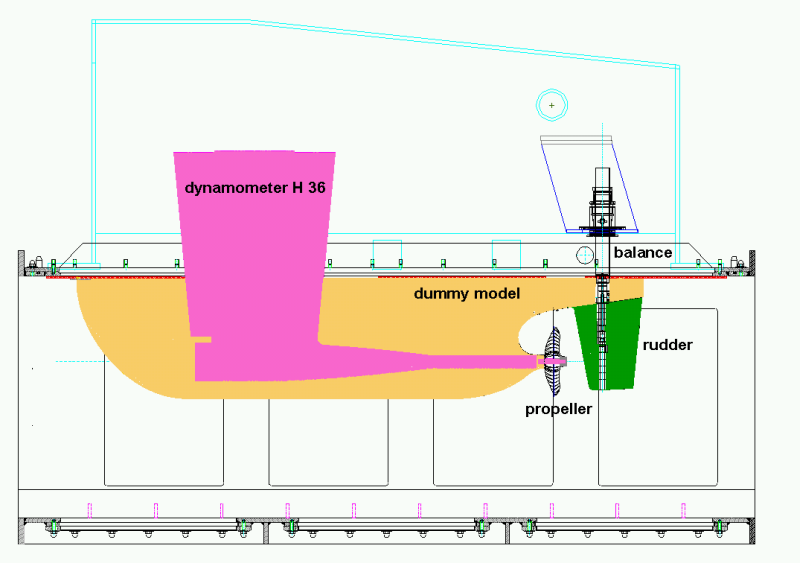
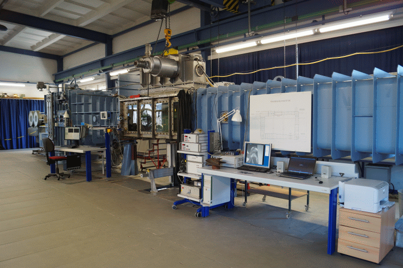
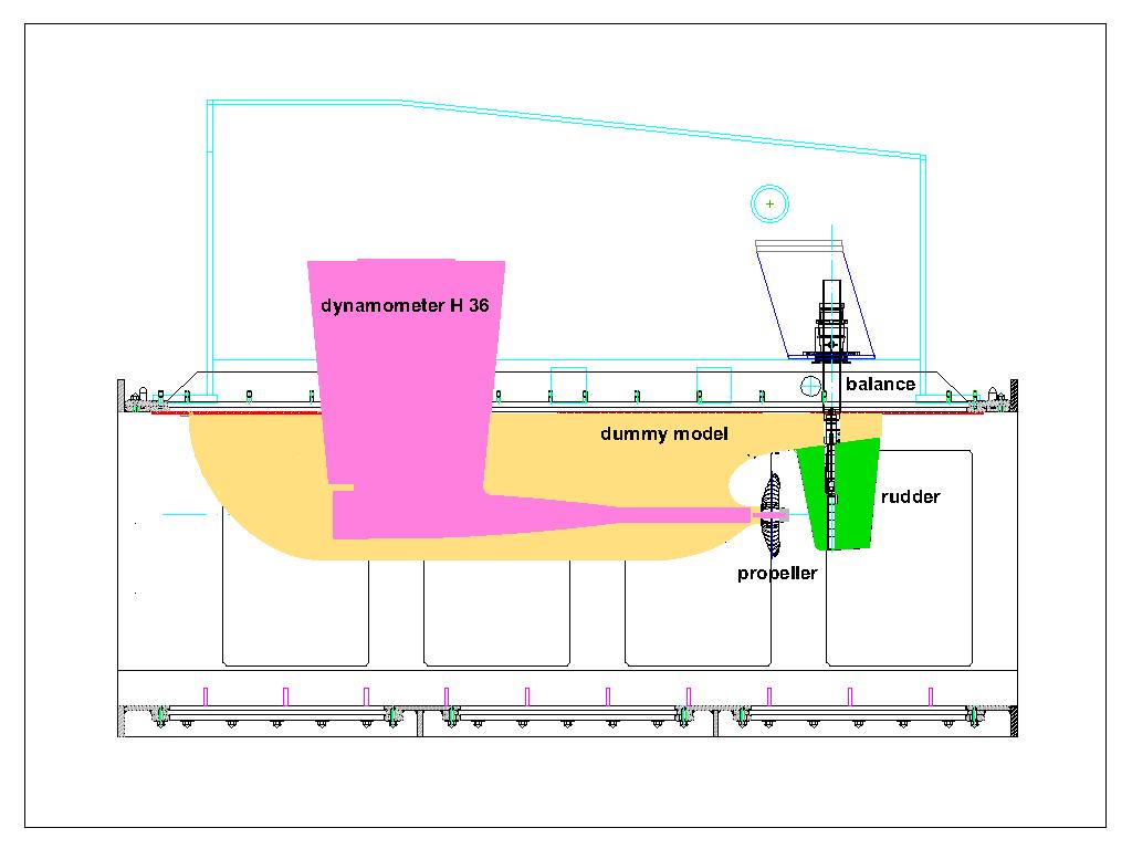
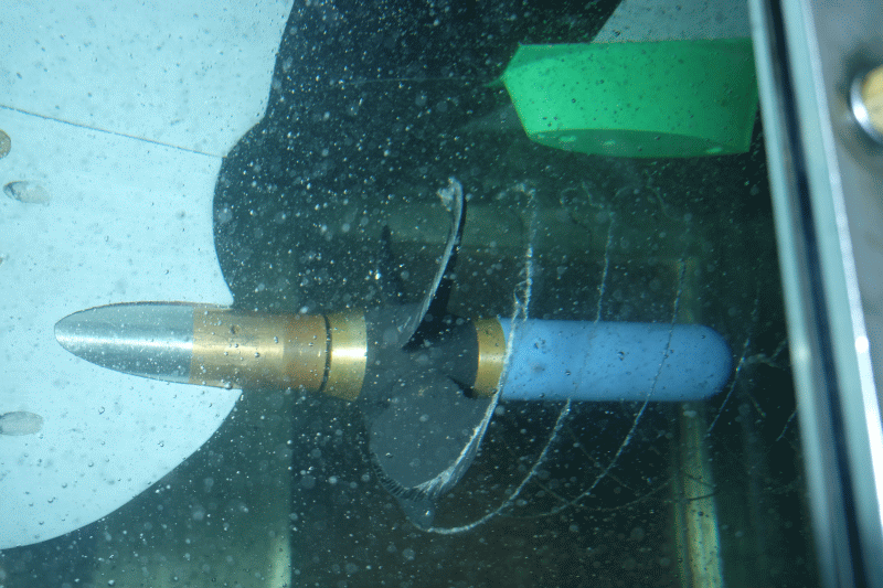
The investigation of the behaviour of propeller cavitation in the wake field of a vessel and measurement of propeller-induced pressure pulses [2] – [6] are carried out in the large test section of the cavitation tunnel. The typical experimental setup for a single-screw vessel is shown in the schematic diagram. The propeller is driven by the dynamometer H36 by Kempf & Remmers. The simulation of the wake, calculated for a Reynolds Number of the full-scale ship, is done with a dummy model and additional grids. The dummy models are up to 2.60 m long and geometrically similar to the ship in the stern area. The blocking of the measuring cross section is within the range between 10 to 22 %. High-Speed recordings of cavitating propulsion systems can be found here.
Context Related References / Research Projects
[1] Potsdam Propeller Test Case: https://www.sva-potsdam.de/en/potsdam-propeller-test-case-pptc
[2] Schmidt, D.: Propellererregte Druckschwankungen an Frachtschiffen mit großen langsamlaufenden Propellern, Schiffbauforschung 26 (1987) 3
[3] Selke, W., Heinke, H.-J.: Propelleruntersuchungen im Kavitationstunnel der Schiffbau-Versuchsanstalt Potsdam, Jahrbuch der STG, 84. Band, 1990
[4] Schmidt, D., Selke, W., Gerchev, G.: Comparative Joint Investigations in the Cavitation Tunnels of SVA and BSHC on the Prediction of Propeller-Induced Pressure Pulses, Schiffbauforschung 31(1992)1
[5] Heinke, H.-J.: Einfluss des Nachstroms auf die Kavitation und Druckschwankungen eines Propellers, 13. SVA-Forum, Potsdam, 29. August 2006
[6] Heinke, H.-J.: The Influence of Test Parameters and Wake Field Simulation on the Cavitation and the Propeller Induced Pressure Fluctuations
Jahrbuch der Schiffbautechnischen Gesellschaft, 97. Band, 2003
- Through the work of the propeller in the irregular wake field, periodically fluctuating forces and moments occur which are introduced via the shaft bearings in the hull.
- The propeller, with its rotating pressure field, generates pulsating compressive forces on the hull. Through the work of the propeller in the irregular wake field additional periodic pressure pulses arise, which can be significantly increased by temporarily occurring cavitation at the propeller blade.
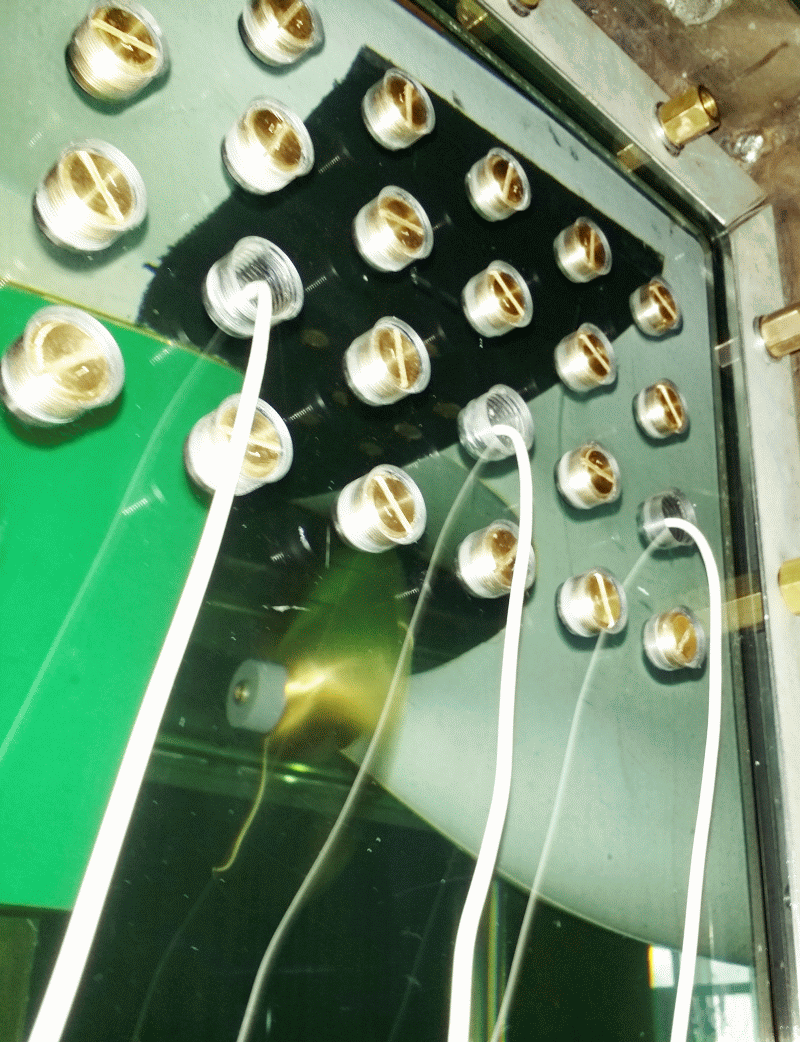
The measurement of the pressure pulses induced by the propeller on the hull of the vessel is accomplished in the large test section (2600 mm x 850 mm x 850 mm) of the cavitation tunnel K15A from Kempf & Remmers [1], [2], [3]. A typical experimental setup for propeller ships is shown. The propeller is driven by the dynamometer H36. Up to 16 pressure sensors are positioned above the propeller in the stern of a dummy model. The length of the dummy models (shortened models with stern contours to scale), is between 2.2 and 2.7 meters. With the dummy model, the predicted three-dimensional inflow to the propeller at the Reynolds number of the vessel is simulated. Within the framework of R & D projects or, for comparison with measurements on ship models, the wake field distribution of the model can be simulated.
Cavitation trials and pressure pulse measurements are based on systematic series of experiments and full-scale measurements to determine and compare the influence of various parameters. The experiments are carried out at high rotational speeds of the propeller model (n > 25 s-1). The oxygen content of the water as a measure of the gas content of the water is controlled at a saturation degree of α / αS > 60%, in order to minimize the influence of the nuclei content of the water and thus the scale effects on the cavitation. In addition, the pressure pulse measurements are performed according to predefined test procedures which, among other things, include a run-in phase of the testing equipment of at least an hour and a range of additional measurements with variations of propeller load and cavitation numbers and variations of the experimental parameters.
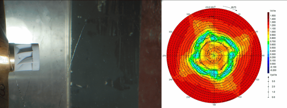
The prognosis and simulation of the inflow at the propeller according to the conditions on the ship is a central point of the R & D work on the development of experimental methods for cavitation trials and pressure fluctuation measurements [4], [5]. Therefore, in preparation for the measurements, CFD calculations are performed for the flow around the ship as well as for the flow around the model. Before carrying out the cavitation and pressure pulse measurements, the velocity distribution in the propeller plane of the dummy model will be measured with the LDV system.
Context Related References / Research Projects
[1] Selke, W.; Heinke, H.-J.: Propelleruntersuchungen im Kavitationstunnel der Schiffbau-Versuchsanstalt Potsdam, STG-Jahrbuch 1990
[2] Schmidt, D.; Selke, W.; Gerchev, G.: Comparative Joint Investigations in the Cavitation Tunnels of SVA and BSHC on the Prediction of Propeller Induced Pressure Pulses, Schiffbauforschung 31/1, 1992
[3] Heinke, H.-J.: The Influence of Test Parameters and Wake Field Simulation on the Cavitation and the Propeller Induced Pressure Fluctuations, Jahrbuch der Schiffbautechnischen Gesellschaft, 97. Band, 2003
[4] Heinke, H.-J.; Hellwig-Rieck, K.: Investigation of Scale Effects on Ships with a Wake Equalizing Duct or with Vortex Generator Fins, Second International Symposium on Marine Propulsors, smp’11, Hamburg, Germany, June 2011
[5] Kleinwächter, A.; Hellwig-Rieck, K.; Ebert, E.; Kostbade, R.; Heinke, H.-J.; Damaschke, N. A.: PIV as a Novel Full-Scale Measurement Technique in Cavitation Research, Fourth International Symposium on Marine Propulsors, smp’15, Austin, Texas, USA, June 2015
The main cause of man-made noise emissions in the sea is currently the propeller. Studies of propeller induced noises are carried out in the form of hydroacoustics, structure-borne noise and pressure pulse measurements, both in model testing as well as for full-scale [1].
The model measurements for determining cavitation noise are performed in the cavitation tunnel. Here hydrophones (on a dummy model or decoupled flow water tank), accelerometers and pressure sensors are used which cover the widest possible frequency range. The measurements and the subsequent scaling of the noise to the full-scale are carried out according to the format recommended by ITTC [2], [3].
In addition to towing tank pressure pulse measurements, hydroacoustic measurements with a hydrophone line consisting of 16 individual hydrophones are carried out when the ship’s model is passing by [3]. To distinguish and localise sound sources, multiple hydrophones are arranged as an “acoustic camera”. This makes it possible to detect and analyse the noise generation at the bow of a model separately from the propeller-induced noise.
Furthermore, onboard measurements for different issues based on the full-scale ship are offered. In addition to underwater sound, far-field measurements with hydrophones from dinghy, as well as pressure pulse and acceleration measurements on the ship are possible.

Themenbezogene Referenzen/Forschungsprojekte
[1] Schulze, R.: Hydroakustik, 5. SVA-Forschungsforum, Potsdam, 26. Januar 2012
[2] Klose, R.; Schulze, R.: Körperschallmessungen zur Prognose kavitationsbedingter Erosion an Schiffspropellern, Kolloquium Kavitation und Kavitationserosion, Ruhr-Universität Bochum, 08./09. Dezember 2014
[3] Klose, R.; Schulze, R.: Körperschallmessungen zur Prognose kavitationsbedingter Erosion an Schiffspropellern, 8. SVA-Forschungsforum, Potsdam, 29. Januar 2015
[4] Schulze, R.: Messung des Propulsions- und akustischen Verhaltens am Heavy Lift Vessel „Anne Sofie“ von SAL, Ges. zur Förderung der SVA, Potsdam, 27. Juni 2014
The risk of erosion of propellers, rudders or appendages is determined mainly by experiment. In the experiments, the erosive effect of the cavitation observed is evaluated and validated by Soft Surface Technique and / or acoustic measurements.
The basis for the erosion tests in the SVA were developed through various R & D projects. In collaboration with the Institute ZWFI “Akademik A.N. Krylov” in Leningrad the Soft Surface Technique was expanded into a method for predicting the erosion intensity [1]. Using this method along with a cavitation generator, parameters of propeller materials (erosion resistance) and erosion coatings were determined. With these values, through experiments, a statement about the risk of erosion and the erosion intensity can be made [2].
In cooperation with the Technical University of Dresden materials were investigated and theoretical methods [3] drawn up to enhance the understanding of the erosion mechanism.
Between 1999 and 2001, with funding from BMBF, the R & D projects “Investigating Layer, Bubble, and Cloud Cavitation and the Associated Erosion Problems” were conducted [4]. During the R & D projects, a new erosion coating was developed and tested in collaboration with the IFL Magdeburg.
Acoustics, which provides another possibility for erosion prediction, is currently being intensively researched as part of the R & D project KONKAV III [5]. Accordingly, erosive cavitation generates different frequency spectra than non-erosive cavitation. On this basis an erosion risk can be detected. The structure borne sound is measured right on the model propeller since the implosion of cavitation bubbles on its surface is responsible for erosion. This kind of erosion detection also offers interesting applications for the real ships on which cavitation monitoring in most cases is very difficult. Based only on the assessment of the frequency spectrum it is possible to determine, without much effort, whether the occurring cavitation is erosive or not.

Context Related References / Research Projects
[1] Selke, W., Mehmel, M.: Modellierung der Kavitationserosion an Propellern im Kavitationskanal, Seewirtschaft, 1 0(1978)4
[2] Georgijewskaja, E. P., Mawljudow, M. A.; Mehmel, M.: Entwicklung einer Methode zur Vorhersage der Kavitationserosion an Schiffspropellern, Schiffbauforschung 3(1981)
[3] Bux, K.: Theoretische und experimentelle Analyse der erosiven Wirkung kavitierender Strömungen auf metallische Werkstoffe, Dissertation, Technische Universität Dresden 1987
[4] Heinke, H.-J.: Untersuchung von Schicht-, Blasen- und Wolkenkavitation und der damit verbundenen Erosionsprobleme, 23. BMBF- Statusseminar Entwicklung in der Schiffstechnik, 18. Oktober 2000, Rostock
[5] Klose, R., Schulze, R.: Körperschallmessungen zur Prognose kavitationsbedingter Erosion an Schiffspropellern, Kolloquium Kavitation und Kavitationserosion, Ruhr-Universität Bochum, 08./09. Dezember 2014
[6] Klose, R., Schulze, R.: Körperschallmessungen zur Prognose kavitationsbedingter Erosion an Schiffspropellern, 8. SVA-Forschungsforum, Potsdam, 29. Januar 2015
The development of ESDs has been worked on already since the 70s. The focus was on the influence of after-body forms and bulges, propulsion and vibration excitation, design and testing of contra-rotating and overlapping propellers, and developing inflow-improving nozzles [1], [2], [3].
Asymmetric after-bodies and guide fins were used in the context of propulsion optimisation of ships for generating a pre-swirl in the propeller inflow to reduce the rotational losses of the propeller. The research and development in this area led to the SVA guide fin systems. Model tests with different types of ships and full-scale measurements show a potential of 2 to 5 % power savings through the use of SVA guide fin systems [4], [5], [6]. Various R & D projects have been processed in order to improve the design of propellers and ESDs. Potential flow methods are used for the design and optimisation of propellers. Viscous calculation methods and experiments are used to verify the design, the prognosis of scale effects and applied to the design and optimisation of propulsion systems such as ducted propellers, thrusters and ESDs. To check the design of the propeller, speed measurements are performed on propeller boss cap fins and rudder. The SVA-developed HVV outlet cover (Hub Vortex Vane), leads to a reduction of the hub vortex and reduces the energy loss of the propeller in the hub area.Systematic CFD calculations are performed for analysis of the effectiveness of Costa Bulb on rudder and to derive design cues [7]. These works were continued in R & D project BossCEff – “Increasing the Effective Degree of Propulsion and Controlling Boss Vortex Cavitation Through Improved Consideration of the Interaction Between Propeller Wash and Boss Cover” [8], [9]. In cooperation with the project partners Technical University of Hamburg-Harburg, The Institute of Fluid Dynamics and Ship Theory (FDS), and the Mecklenburger Metallguss GmbH (MMG), special propeller flow caps were developed and studied for use in rudders with Costa Bulbs and propeller boss covers with fins.
The Mecklenburg Metallguss GmbH developed in the collaborative projects BossCEff a new energy-saving propeller cap, MMG ESCAP®.
The propeller caps improve propulsion characteristics of the vessel on existing propellers and on propeller redesign projects. The ESCAP®, among others, has also been successfully applied in newly designed propellers.
The following maximum power savings were achieved for ships with ESDs by investigations of SVA [11], [12]:
| – Twisted Rudder | up to 1,4 % |
| Costa-Bulb with Twisted Rudders | up to 3,7 % |
| Costa-Bulb with Conventional Rudders | up to 3,5 % |
| Boss Cap Fins | up to 3,2 % |
| Propeller Redesign | up to 14 % |
| Wake Equalising Duct | up to 4,8 % |
| Becker Mewis Duct® | up to 10 % |
| Bulbous Bow Retro-fit | up to 21 % |

Context Related References / Research Projects
[1] Schmidt, D.: Propulsionsuntersuchungen mit Einzelpropeller und Gegenlaufpropeller am Modell eines Containerschiffes, Schiffbauforschung 14 1/2/1975
[2] Schmidt, D.: Der Einfluss der Form des Heckwulstes auf die Schwingungserregung durch den Propeller für ein Containerschiff, Schiffbauforschung 21 1/1982
[3] Schmidt, D.: Die Reduzierung der propellererregten Schwingungen durch nachstrombeeinflussende Änderungen am Hinterschiff,
Schiffbauforschung 23 3/1984
[4] Mewis, F., Peters, H.-E.: Verbesserung der Propulsion durch ein neuartiges Flossensystem Intern. Rostocker Schiffstechnisches Symposium, Schiffbauforschung, Sonderheft, Bd. 1, 1987
[5] Peters, H.-E., Mewis, F.: Das Leitflossensystem der SVA am Containerschiff Typ Saturn, HANSA Nr. 17/18, 1990
[6] Schmidt, D.: Nachrüstung von Motorgüterschiffen ermöglicht Leistungseinsparung, Binnenschiffahrt – ZfB Nr. 9, Sept. 1995
[7] Lübke, L.: Numerical Simulation of the Viscous Flow around Costa Bulbs, NUTTS 2002, Nantes, August 2002
[8] Greitsch, L., Pfannenschmidt, R., Abdel-Maksoud, M., Druckenbrod, M., Heinke, H.-J.: BossCEff – Steigerung des Propulsionswirkungsgrades durch Reduktion von Nabenwirbelverlusten, Statustagung „Maritime Technologien“, BMWE, Rostock, 10.12.2014
[9] Heinke, H.-J., Lübke, L. O., Steinwand, M.: Numerical and experimental investigations for influencing the propulsion efficiency in the hub region of the propeller, STG-Sprechtag “Hydrodynamic Performance of ESDs”, Hamburg, 09.10.2014
[10] Pfannenschmidt, R.; Greitsch, L.: Das MMG Re-Design-Programm, Hanse Sail Business Forum, 07.08.2014
[11] Heinke, H.-J., Lübke, L. O.: Maßnahmen zur Energieeinsparung, Schiff & Hafen, Nr. 10, 2014
[12] Heinke, H.-J., Hellwig-Rieck, K.: Investigation of Scale Effects on Ships with a Wake Equalizing Duct or with Vortex Generator Fins, Second International Symposium on Marine Propulsors, smp’11, Hamburg, Germany, June 2011
Please read more about our 3 components LDV system here.
The process is very versatile. So far the following measuring tasks, among others, have been undertaken:
- Flow fields in the wake of ship models with and without working propellers
- Rudder dynamics with gap flow
- Decay of vortices on a generic wing
- Vortex flow around bilge keels
- Propeller wash of a thruster on a semi-submersible platform
- Propeller wash in the cavitation tunnel
- Flow around and wake of a submarine model with tower
- Flow around profile sections in the cavitation tunnel
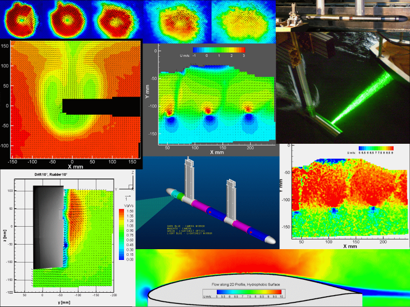
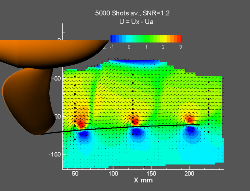
With PIV the whole velocity field is measured in every frame. From the individual recordings the transient evolution of the flow can be visualized and also a mean velocity field can be determined by averaging all recordings. The desired spatial resolution determines the size of the field of view and the achievable number of vectors in the measuring range. The largest achieved measuring range so far had an extension of approximately 400×600 mm, in this case about 6000 vectors. For this task, a stereoscopic PIV system from the company TSI is used. It has a modular design, so that all symmetrical, asymmetrical and independent arrangements of cameras and light sheet can be realized. Thus, for example, it is possible to measure the full depth of the towing tank.
Please read more about the technical specifications of this PIV system here.

Context Related References / Research Projects
[1] Anschau, P.: Stereoskopische PIV-Messungen in Schlepprinne und Kavitationstunnel, Workshop Optische Strömungsmessverfahrenr, TU Dresden, 9. März 2011
[2] Anschau, P.: Stereoskopische PIV-Messungen an tiefgetauchten Schleppkörpern, TSI Seminar , Potsdam, 17. Oktober 2012
[3] Kleinwächter, A., Hellwig-Rieck, K., Ebert, E., Kostbade, R., Heinke, H.-J., Damschke, N. A.: PIV as a Novel Full-Scale Measurement Technique in cavitation Research, Fourth International symposium on Marine Propulsors, smp´15, Austin, Texas, USA, June 2015

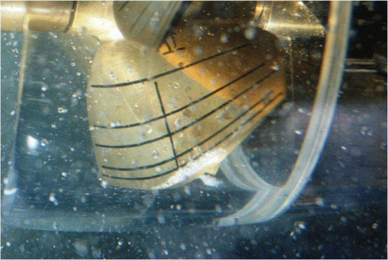
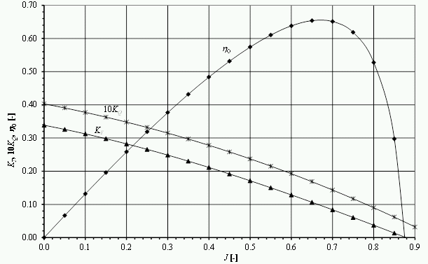
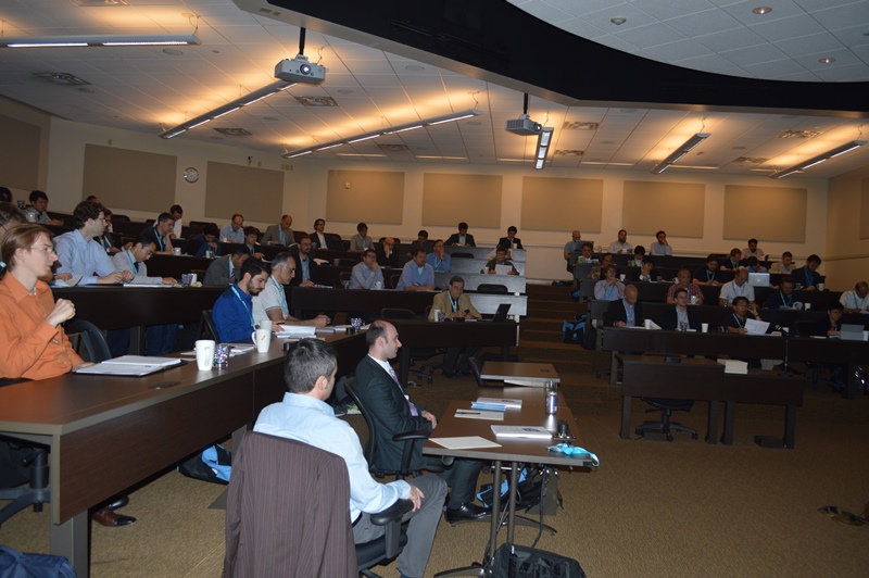
The Potsdam Propeller Test Case (PPTC) is a program for the validation of calculation methods for propellers. The PPTC propeller has been specially designed to enable researchers to validate calculation methods for propeller cavitation. The SVA design VP1304 (PPTC-Propeller) has, beside good hydrodynamic qualities, pronounced tip vortices, suction side and pressure side cavitation, root and bubble cavitation, and therefore is well suited for validation purposes.The open water characteristics of the propeller were measured at 0 ° and 12 ° shaft inclination. In selected points of operation the cavitation was recorded on the propeller optically. Additionally, extensive velocity measurements in the area of the blade tip as well as pressure fluctuation measurements were carried out. Within the framework of the International Symposium on Marine Propulsion in 2011 and 2015 respectively, a workshop has been organised on cavitation and propeller performance. In these workshops, the results of calculations from different tools were presented, analysed, and discussed and also compared with the experimental results.
For both workshops, the geometries, measurements, evaluations, reports and presentations are available on the website of the SVA (smp’11 and smp’15). The Proceedings of smp’11 and smp’15 also include presentations of the 1st and 2nd Workshop on Cavitation and Propeller Performance (www.marinepropulsors.com). The PPTC is also used by the ITTC as a benchmark for propeller calculations.
PPTC leads to various published data on the Potsdam Propeller Test Case and related projects.


Context Related References / Research Projects
[1] smp’11: 2nd Symposium on Marine Propulsors & 1st Workshop on Cavitation and Propeller Performance, June 17 -18, 2011, Hamburg, Germany
[2] smp’15: 4th Symposium on Marine Propulsors & 2nd Workshop on Cavitation and Propeller Performance, May 31 – June 4, 2015, Austin, Texas, USA

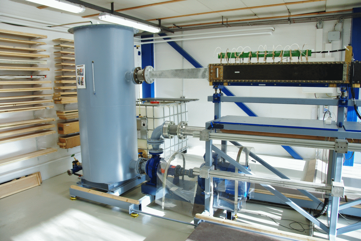
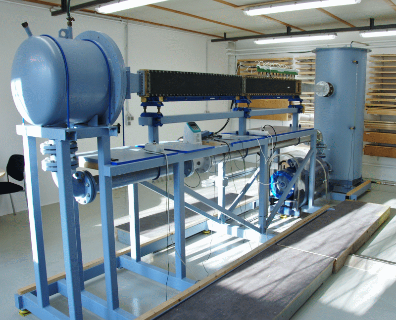
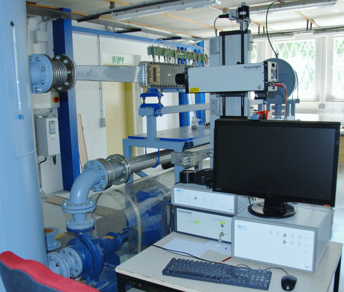
The frictional resistance of a ship is a substantial part of the total resistance. This is influenced, among other things, by the texture of the skin (e.g., type of coating, degree of fouling). To minimise the power consumption and thereby reduce costs and protect the environment, it is therefore sensible to hold frictional resistance as low as possible by special coatings or surface structures. Corresponding studies can be performed on the friction measuring system. A roughness analysis of the surface by itself is not sufficient to deduce the exact frictional resistance. Experimental studies allow for more accurate conclusions. For this purpose, two plates with the coating to be tested are installed so that these form a narrow rectangular channel which is traversed by water in the friction test section. By the simultaneous measurement of the flow rate and the pressure loss along the test section and the water temperature, the wall shear stress can be detected and finally the frictional resistance coefficient of the plates is calculated. The results are transferrable to the frictional resistance of the ship. In order to cover the largest possible range of speeds, up to 20 m/s can be run in the friction measuring system.
These studies are not limited to the shipbuilding industry, but are also applicable in the aerospace and automotive industries. The results from the friction measuring system are also transferrable for these applications and can be profitably implemented where friction plays a role.

Context Related References / Research Projects
[1] Schulze, R.: Measurement of Skin Friction Drag and Design of Riblet Structures for a Ship Application, AIRBUS, Bremen, 30. Juni 2015
Please enable JavaScript! To use the SVA-Website, please enable JavaScript