Ship
Good ship lines are the basis for the efficient and safe operation of a vessel. Clients of SVA are supported in the development of optimal ship lines by experienced engineers and the use of effective calculation tools. The design process takes place in close cooperation with the client and is accompanied by CFD calculations. With the results of the CFD calculations, a speed and performance prediction can be created. For lines development at the SVA Potsdam, the programs CAESES and DELFTship Professional are used. The CFD calculations are performed with the viscous CFD solvers ANSYS CFX and Fluent. In order to assess the seakeeping behaviour of a ship design, the SVA Potsdam uses the UTHLANDE program package.
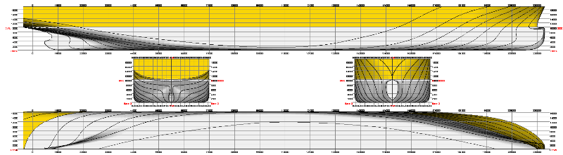
If the main dimensions are not fixed, the SVA Potsdam provides parametric studies according to the prescribed specifications. By means of CFD calculations, statistical methods and the SVA database the best values for parameters such as main dimensions (L, B, T) or coefficient (CB, CM, LCB …) are hereby determined. From this, the impact of changes in various shape parameters can be determined on the performance of the vessel.
Context Related References / Research Projects
[1] Abdel-Maksoud, M.: Advantage of Application of CFD Methods in Ship Form Development, AEA – SVA Forum, Potsdam, 23rd March 2001
[2] Grabert, R., Rieck, K.: Hull Form Optimisation of Ferries Using CFD, 10. SVA-Forum, Potsdam, 26. Juni 2003
[3] Lübke, L.: STG 2009 – CFD-basierte Schiffsformoptimierung CFD-Sprechtag der STG, Hamburg, 25. September 2009
[4] Steinwand, M.: High Efficiency Design in der SVA, 5. SVA-Forschungsforum, Potsdam, 26. Januar 2012
[5] Lübke, L.: CFD in Ship design, ANSYS Conference & 32nd CADFEM Users` Meeting 2014
Please read here more about simulation driven hull optimization.
The performance prediction is the basic task of model basins.
Performance Prediction Based on Model Tests
With the aid of model tests the required propulsion power for all types of vessels is determined. The classic performance prediction is based on
- resistance tests
- open water tests
- and propulsion experiments.
As a result of these tests, all performance parameters can be identified. The extrapolation of the model test results takes place either without determining the form factor, or in accordance with the ITTC 1978 Performance Prediction Method with form factor. Both methods are well established and provide reliable results for the most cases. The SVA performs the propulsion tests by applying the British method.
Prerequisite for the extrapolation of the test results is high accuracy in measuring and in the model finish. The SVA complies with the requirements of the ITTC (International Towing Tank Conference) for all areas of the test system. Advanced measuring and analysis technology helps the test engineer and reduces the time required to carry out the tests. The experimental results and procedures are continuously verified and validated.
Performance Prediction Based on Statistical Data
Based on the SVA database and various empirical methods the SVA is able to create a quick performance prediction [1]. This enables a first estimate of the power requirement of a watercraft in the early design stage.
Performance Prediction Based on Viscous CFD Calculations
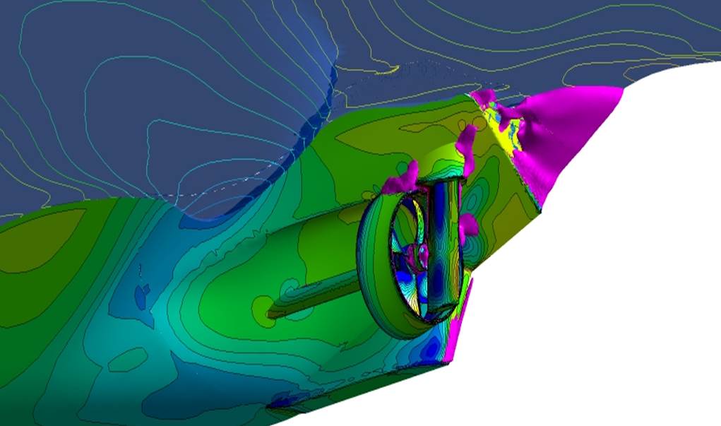
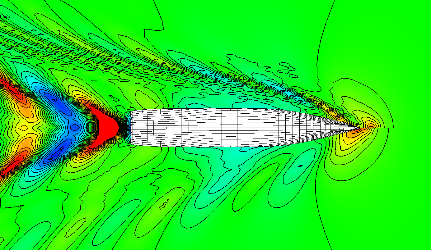
In viscous CFD simulations (Computational Fluid Dynamics), the flow about the geometry and the resulting resistance and the wake field will be calculated in the scales of full size and / or the model scale. Based on these calculations the potential of possible improvements of the ships lines can be detected. In order to include the effect of the working propeller on the ship resistance, the propeller effect can be simulated or the real propeller geometry taken into account in further CFD calculations. From the calculated resistance within given propulsion conditions or from the calculated torque, the delivered power can be determined. If no custom propeller data is available, the polynomials of the Wageningen B-series are alternatively used for this purpose.
The performance prediction based on viscous CFD calculations [2] is for many cases an alternative to model testing, especially when only individual operating points are required. The results can still be used for general ship evaluation, motor design, and as a basis for the propeller design.
Context Related References / Research Projects
[1] Grabert, R.: Ein Verfahren zur Leistungsprognose nach Vergleichsschiffen, Schiffbauforschung 31(1992)1
[2] Rieck, K., Hellwig-Rieck, K.: Numerische Propulsionsprognose von Schiffen, STG-hauptversammlung, Rostock, November 2011

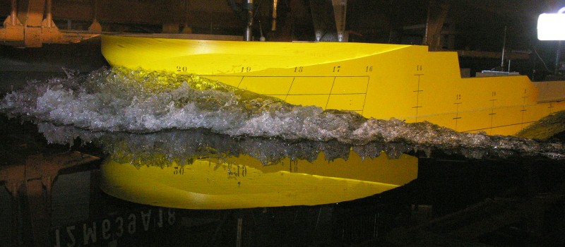
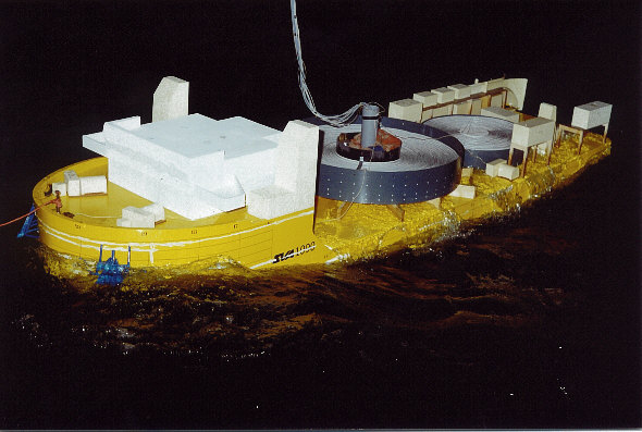
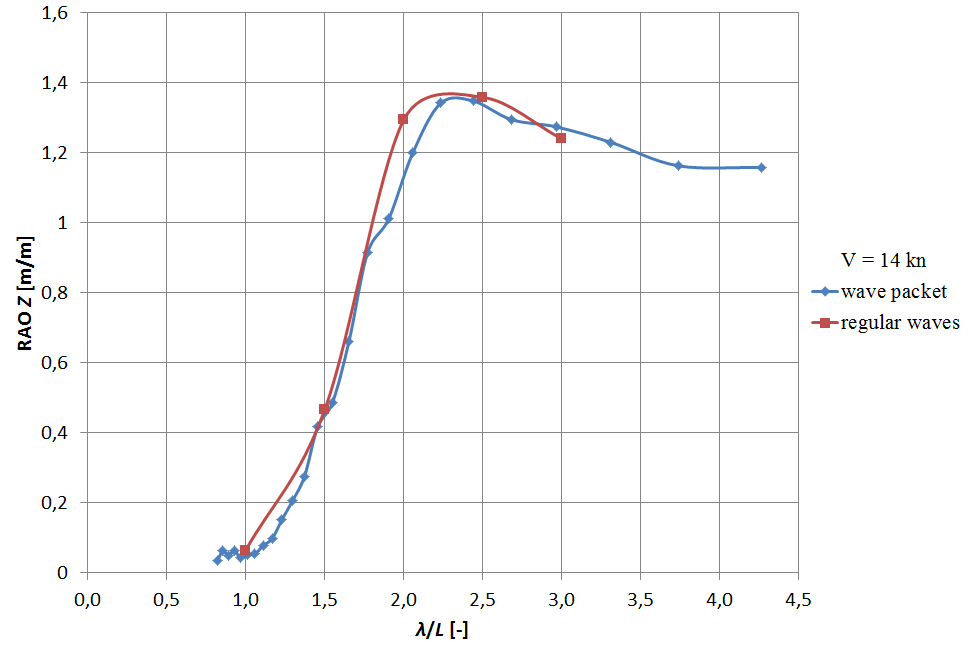
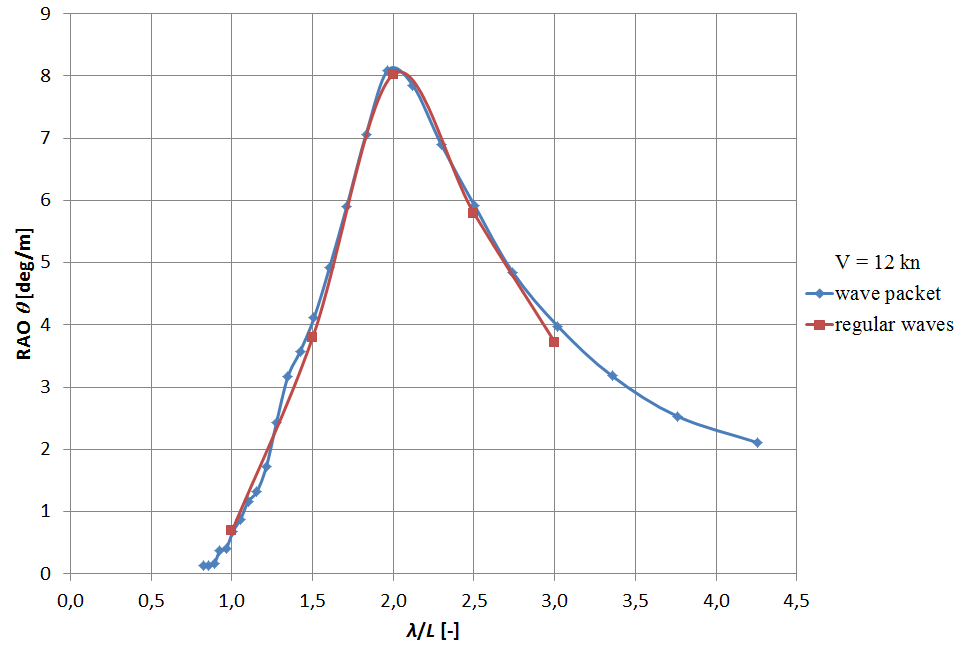
The seakeeping of the ship can be determined in regular and irregular sea states and in wave packets. A cavitation tunnel (Kempf & Remmers) with modern measurement technology is available for the study of the working propeller under cavitation similarity.
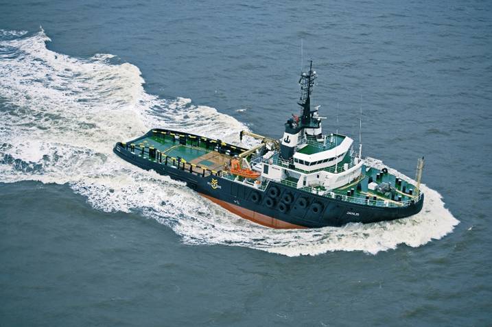
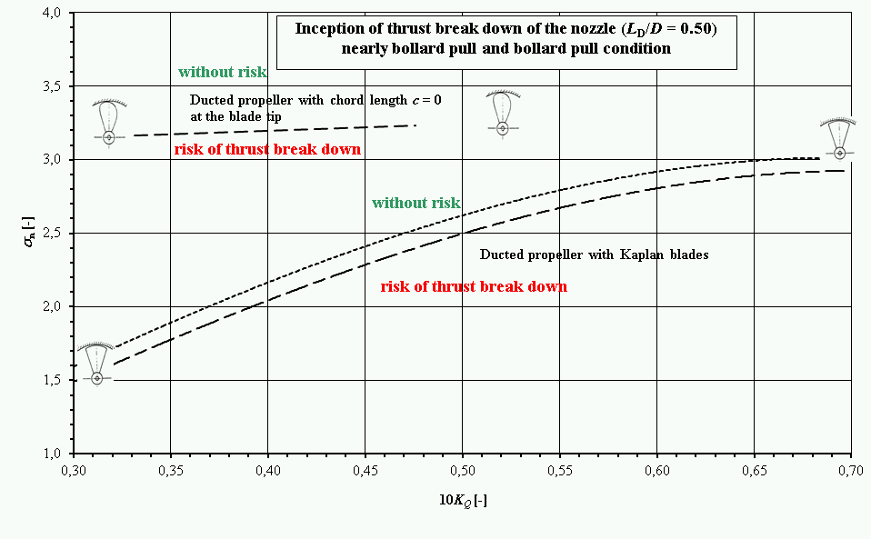
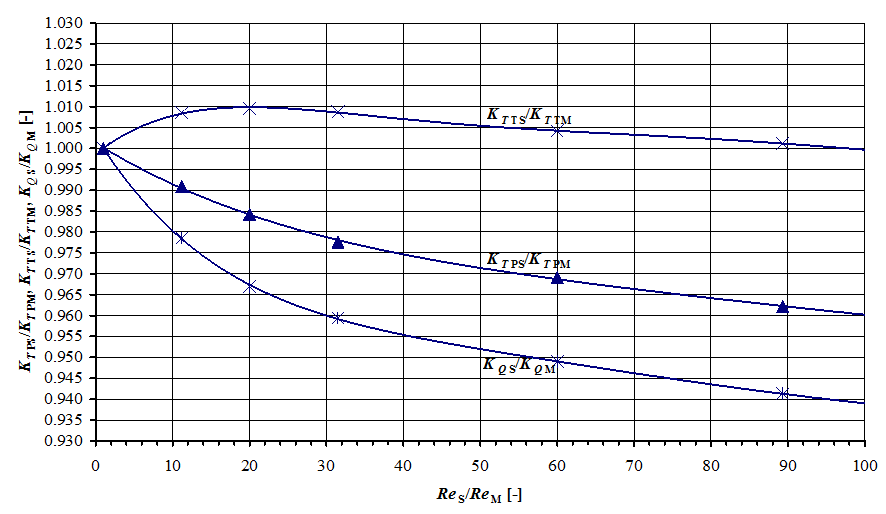
In R & D projects “Correlation of Z-drive with Ducted Propellers” the findings in the field of CFD calculations have been successfully applied for the systematic numerical investigation of ducted propellers [1]. The established references and procedures for Reynolds number correction are an important basis for the evaluation of experiments with ducted propellers or thrusters with ducted propellers to full-scale. In the R & D project “Increasing the Design Reliability of Ducted Propeller Systems at Bollard Pull Conditions” and ” Reynolds Number Effects on the Bollard Pull Prediction” the process of bollard pull prediction with tugboats having a ducted propeller arrangement was analysed [2], [3]. In particular, the findings related to the cavitation thrust break down of the ducted propeller at high load levels are now an integral part in the design process of propulsion system. With the chart worked out by the SVA for estimating the risk of cavitation induced thrust break down, the need for cavitation testing can be determined.
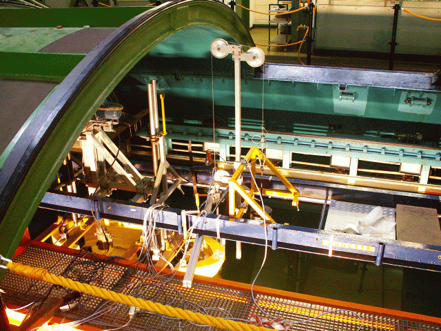
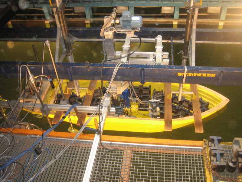
Extensive investigations of cavitation on the propulsion systems of tugs were conducted in the cavitation tunnel of the SVA and the large circulation and cavitation tunnel (UT2) of the TU Berlin [2], [3], [4], [5]. Among others, bollard pull tests with cavitation similarity between models of Voith Water Tractors and AHTs (VWT) were conducted. In the R & D projects “Forecasting Reliability for the Power Requirement of Tugs with Ducted Propeller Systems”, geosimulation experiments and comprehensive CFD calculations were carried out. These results were used to analyse the scale influences on the propulsion prediction for tugs. The results of measurements and calculations were compared with full-scale measurements of AHTs and integrated into the predicting procedures.
Context Related References / Research Projects
[1] Abdel-Maksoud, M., Heinke, H.-J.: Scale Effects on Ducted Propellers, 24th Symposium on Naval Hydrodynamics, Fukuoka, Japan, 2002
[2] Mertes, P., Heinke, H.-J.: Aspects of the Design Procedure for Propellers Providing Maximum Bollard Pull, ITS 2008, Singapore, 2008
[3] Heinke, H.-J., Hellwig, K.: Aspekte der Pfahlzugprognose für Schlepper großer Leistung,104. Hauptversammlung der Schiffbautechnischen Gesellschaft, Hamburg, 2009
[4] Heinke, H.-J.: Model tests with Voith Schneider Propellers at high thrust coefficients, Hydrodynamic Symposium – Voith Schneider Propulsion, Heidenheim, March 2006
[5] Heinke, H.-J.: High-Speed Camera Observations of the Cavitation at a Voith Schneider Propeller, 2nd Symposium Voith Schneider Technology, Heidenheim, June 2008
[6] Heinke, H.-J., Grabert, R.: Influence of the Reynolds number on the characteristic of ducted propellers, 68. Sitzung des FA “Schiffshydrodynamik” der STG, Hamburg, 08.10.2014
Context Related References / Research Projects:
[1] Grabert, R.: Analysis of the Interaction VSP – Hull of Modern OSV, 4th Voith Symposium, Heidenheim, 12. – 14. Juni 2012
[2] Heinke, C.: Offshore Support Vessel mit zwei Voith Schneider Propellern, Bericht 4310, Schiffbau-Versuchsanstalt Potsdam, Dezember 2014 (Abschlussbericht)
[3] Heinke, C.: Investigations of OSV with VSP propulsors at SVA Potsdam, 5. Hydrodynamisches Symposium on Voith Schneider Propulsion, Heidenheim, 30.09. – 02.10.2014
[4] Heinke, C.: Offshore Support Vessel mit Voith Schneider Propeller, 8. SVA-Forschungsforum, Potsdam, 29. Januar 2015
[5] Steinwand, M.: Dynamic Positioning mit Motionstabilisierung („DP Motion“), 8. SVA-Forschungsforum, Potsdam, 29. Januar 2015
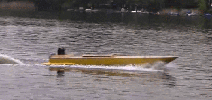
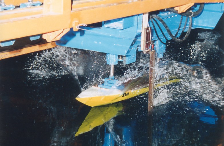
The SVA examines and optimises planing and semi-planing hulls with regards to their dynamic riding characteristics in displacement and planing modes. This includes, among other things, investigations concerning constructive measures which encourage early and stable “planing” and ensure a stable trim while on plane. In all considerations, low power consumption, stability and seaworthiness are the focus of investigations. Dynamic performance of speedboats can be studied both experimentally and numerically. Doing this, optimum solutions can be found through specific modifications and adjustments to the model. The range of services provided by the SVA regarding planing includes following study focuses:
- Resistance and propulsion tests
- Finding an optimal interceptor settingg
- Optimal center of gravity
- Optimal stern wedges or planing flaps
- Design and testing of the spray rails
- Manoeuvring tests in the field
- Testing of lifting strakes
Context Related References / Research Projects
[1] Schomburg, E.: FuE-Projekt „Gekoppeltes CFD-Verfahren zur Widerstandsprognose von Schiffen im Gleitzustand“
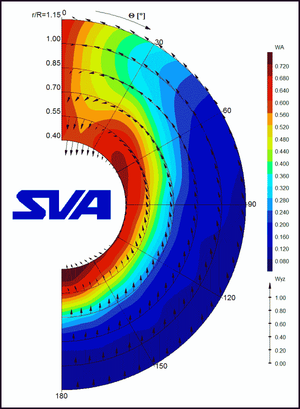

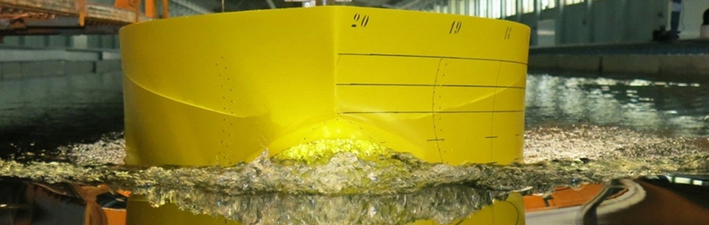
- Measurements in the propeller plane
- Measurements at the point of appendages, ie. the shaft struts
- With the probe, any coordinates can be approached
- 3-Dimensional wake field measurement
The standard measurement of a wake field for single screw vessels is carried out on 6 radii respectively, every 5 °. For measurements behind podded drives and shaft struts among others, the resolution is adjusted accordingly.
In addition to the experimental determination of the wake field, a calculation based on CFD simulation is possible. An advantage of a CFD simulation is the calculation of the velocity field for the Reynolds number of the full-size version.
Context Related References / Research Projects
[1] Anschau, P., Mach, K.-P.: Application of a Stereo PIV System for Investigations of Flow Fields in Towing Tank and Cavitation Tunnel, HYDRONAV 2007, Wroclaw, Polen, September 2007
[2] Grabert, R.: Der Einfluss unterschiedlichster Betriebszustände eines Schiffes auf das Nachstromfeld, 3. SVA-Forschungsforum, Potsdam, 28. Januar 2010:
[3] Lübke, L.: Formoptimierung unter Berücksichtigung der Charakteristik des Nachstromfeldes, 4. SVA-Forschungsforum, Potsdam, 27. Januar 2011
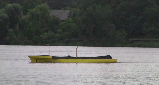
Full-scale measurements are performed with our own team and recording system (DGPS). In addition to determining the manoeuvring behaviour of full-scale and measured miles trials, the SVA executes, performance, vibration and noise measurements, and cavitation observations.

Context Related References / Research Projects
[1] Steinwand, M.: SLOWMAN – Manövrieren bei kleinen Geschwindigkeiten, 4. SVA-Forschungsforum „Theoria cum Praxi“, Potsdam, 27. Januar 2011
[2] Steinwand, M.: Manoeuvrability of a Single Screw Ship with Pod, HYDRONAV’03, Gdansk 22. – 23. October 2003
[3] Steinwand, M.: Maßstabseffekte bei der Bestimmung des Manövrierverhaltens von Unterwasserfahrzeugen durch Modellversuche, 2. SVA-Forschungsforum „Theoria cum Praxi“, Potsdam, 29. Januar 2009
[4] Weede, H.: System identification of manoeuvring ship models, Report accompanying the lecture hold at SVA on Nov 26, 2001
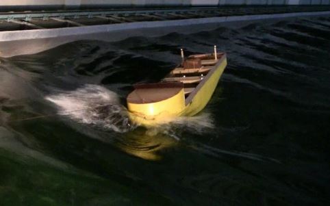
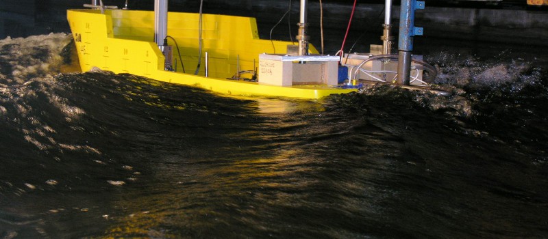
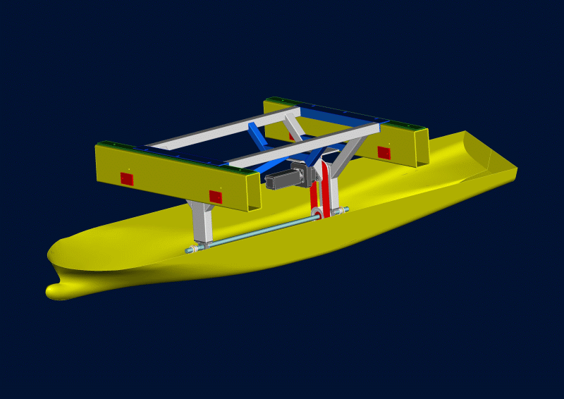
Seakeeping tests can be carried out in countering and following seas as well as quartering seas at an angle of up to 35° off course. The latter takes the form of zigzag driving, which is recognised by the classification societies as an experimental technique. The motion behaviour of tested objects is detected with a high resolution optical tracking system. This system allows contactless measurement of the coupled motions of two-body systems in all 6 degrees of freedom as well as speed and acceleration at defined positions.
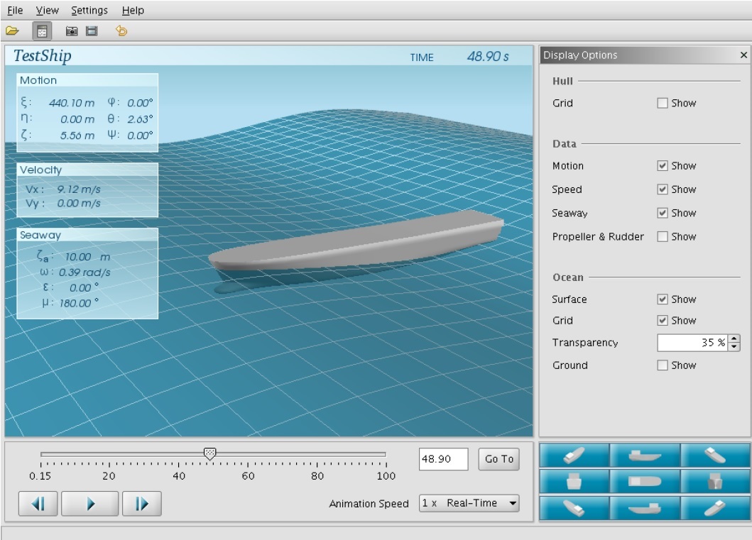
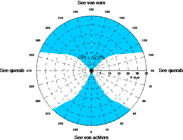
For numerical simulations of sea keeping the UTHLANDE program system is available. Based on linear and non-linear strip method, this system allows the calculation of the motions and loads of mono hull ships and catamarans for all 6 degrees of freedom. The program provides the statistical characteristics (short and long term statistics) for long and short crested seas represented in Cartesian or polar diagrams and a video animation based on a “ship motion viewer”. The process provides valuable insights by varying different sea state specific parameters in the optimisation process and serves as a valuable support of model experiments.
Context Related References / Research Projects
[1] Fröhlich, M.: Experimentelle und rechnerische Analyse von Slammingbelastungen im Seegang, Ermittlung von Koeffizienten zur Abschätzung von Slammingbelastungen, SVA-Potsdam, 16.02.2000
[2] Fröhlich, M.: Ermittlung der Wasserübernahme bei Schiffen im Seegang mit Hilfe der Anwendung moderner Ultraschalltechnik, 1. SVA-Forschungsforum, Potsdam, 31. Januar 2008
[3] Fröhlich, M.: Wasserübernahme und parametererregte Rollschwingungen bei Schiffen im Seegang, Mitgliederversammlung, Verein zur Förderung der SVA e.V., 18. Dezember 2008
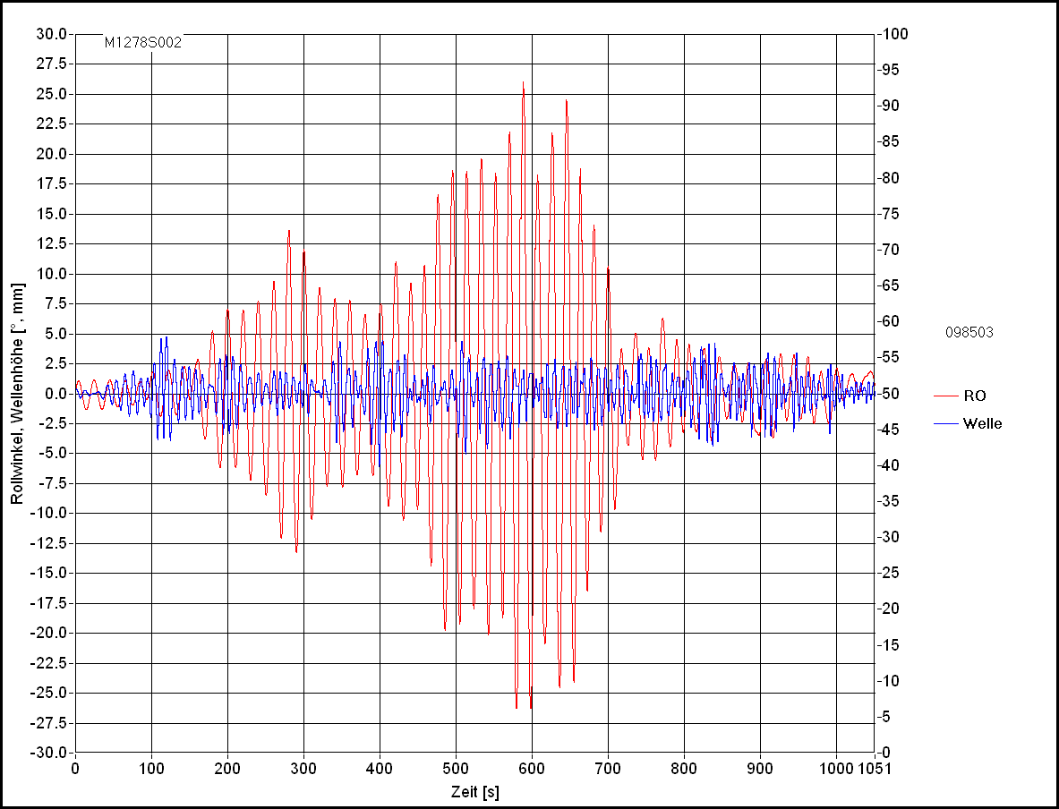
The SVA has a system that causes forced rolling motions of ship models with variation of rolling amplitude and frequency, with and without forward motion. By doing this, the rolling moment can be measured.
Parameterically excited rolling can be simulated with the ROLF method (nonlinear strip method), which has been integrated into the UTHLANDE program system. For a quick estimate of the risk of a ship with respect to parameterically excited oscillations, an SVA developed method is used which provides, based on fluctuations in metacentric heights, an indicator as to whether a rollover impulse is to be expected for a combination of ship speed, wave height and wavelength.
For the selection of roll damping tanks, calculation methods are available that allow both Frahm and box tanks to be analysed.
For large yachts and cruise ships in particular, stabiliser fin systems are available with corresponding geometries which damp rolling even while the vessel is stationary. The roll damping rates of these and similar systems are determined in the towing tank by applying different wave conditions to the model.
Context Related References / Research Projects
[1] Fröhlich, M., Nietzschmann, T., Wuttke, H.: Untersuchung der parametererregten Rollschwingungen bei modernen Containerschiffen, Kolloquium Schiffstechnik, Uni Rostock, 21 Januar 2011
[2] Fröhlich, M., Schumann, C.: Simulationsverfahren zur effizienten Bestimmung großer Rollbewegungen von Schiffen, 5. SVA-Forschungsforum, Potsdam, 26. Januar 2012
[3] Fröhlich, M.: Experimentelle und theoretische Untersuchungen zur Rolldämfung, 6. SVA-Forschungsforum, Potsdam, 31. Januar 2013
[4] Fröhlich, M.: ROLLTANK – Weiterentwicklung und Validierung von theoretischen Verfahren zur Vorhersage der Rollbewegung von Schiffen unter Berücksichtigung von Rolldämpfungstanks, 8. SVA-Forschungsforum, Potsdam, 29. Januar 2015
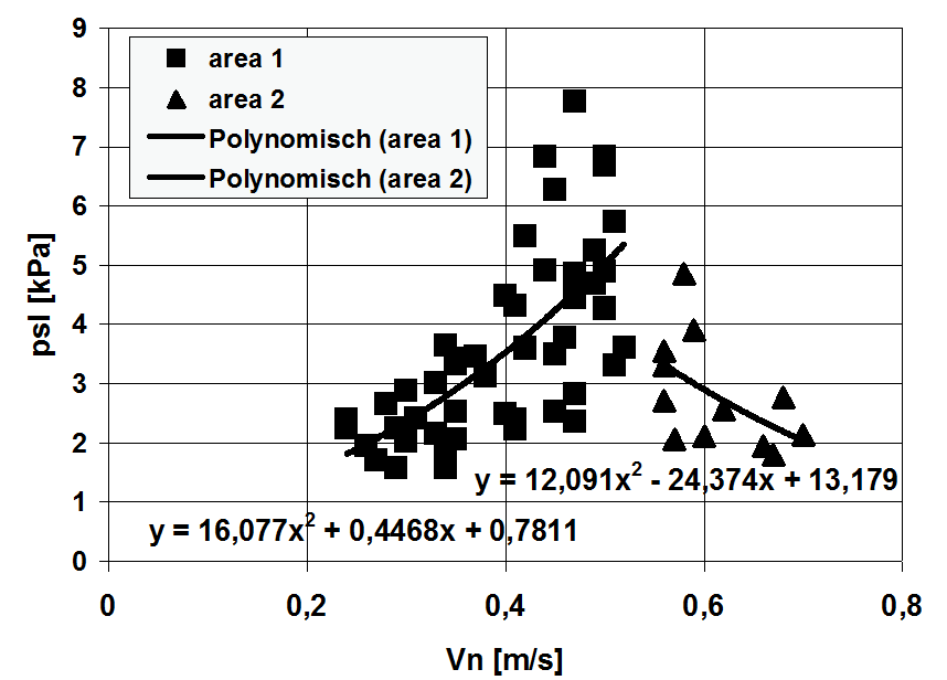
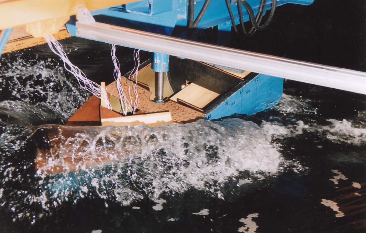
The equiping of models with miniature pressure sensors of different sizes allows the measurement of slamming pressures on vulnerable positions of the hull in the model test under extreme sea conditions, both when driving and when stationary. Moreover, slamming pressures can also be measured with regular seakeeping tests.
Slamming phenomena are also simulated with existing CFD tools. The UTHLANDE program serves to determine slamming prevalence. For a quick estimate of slamming pressures the SVA has developed a simplified procedure. It is based on results of systematic model tests and allows the determination of slamming pressure for any hull shape, for a given speed and location on the vessel. An important parameter is the velocity normal to the hull and the fluid at the point of interest of the hull surface. Areas with air entrapment (hull slamming) can therefore not be detected.
As a result, the processing of various R & D projects [1], [2], the [3] SVA has a wealth of experience in investigating slamming phenomena.
Context Related References / Research Projects
[1] Fröhlich, M.: Einsatz eines Schwingungsoszillators auf hydraulischer Basis zur Untersuchung der Slammingbelastung von Schiffen, STG-Sprechtag „Schiffe im Seegang“, Hamburg, Oktober 1998
[2] Fröhlich, M.: Slammingbelastungen von Schiffen, Freitagsvorlesung an der TU-Berlin, 25.06.99
[3] Fröhlich, M.; Hellwig, K.: Numerical and experimental investigations of slamming loads for fast ships, HIPER`01, Hamburg May 2001
[4] Fröhlich, M.; Hellwig, K.: Untersuchungen zum Slammingverhalten schneller Schiffe, 6. Schiffbautag Mecklenburg-Vorpommern, Rostock, Oktober 2002
Trim optimisation tests have already been carried out as standard procedure since 1970. As a result of the R & D project “Effective Trim Optimisation for Cargo Ships” [1] it has been possible to improve the predicting methods of power savings (calculated trim optimisation) as well as the experimental trim optimisation. The methods have different approaches from a purely statistical analysis of extensive model test series up to CFD simulations of entire trim matrices:
- Prediction of the resistance of the ship for different draughts with or without combinations of various trim states using the resistance method according to Danckwardt and / or the SVA-LSR method
- Formulas for determining the influence of partial discharging and / or trimming characteristic values on the propulsion
- Hybrid procedure: Predicting of resistance and propulsion for partial discharging and / or trimming by coupling parts of the process of resistance according to Danckwardt / SVA LSR method with experimental results
- Trim optimisation through pilot projects (EFD)
- Trim optimisation through CFD calculations (CFD)
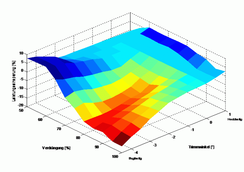
As a result, master and officers may set the optimum trim condition for the ship using the information provided by the methods mentioned above. The 3D contour plot shows an example of the dependence of the power saving on displacement and trim.
Context Related References / Research Projects
[1] Heinke, C.: Effektive Trimmoptimierung für Frachtschiffe, Bericht 4394, Schiffbau-Versuchsanstalt Potsdam GmbH, Juni 2015, Abschlussbericht

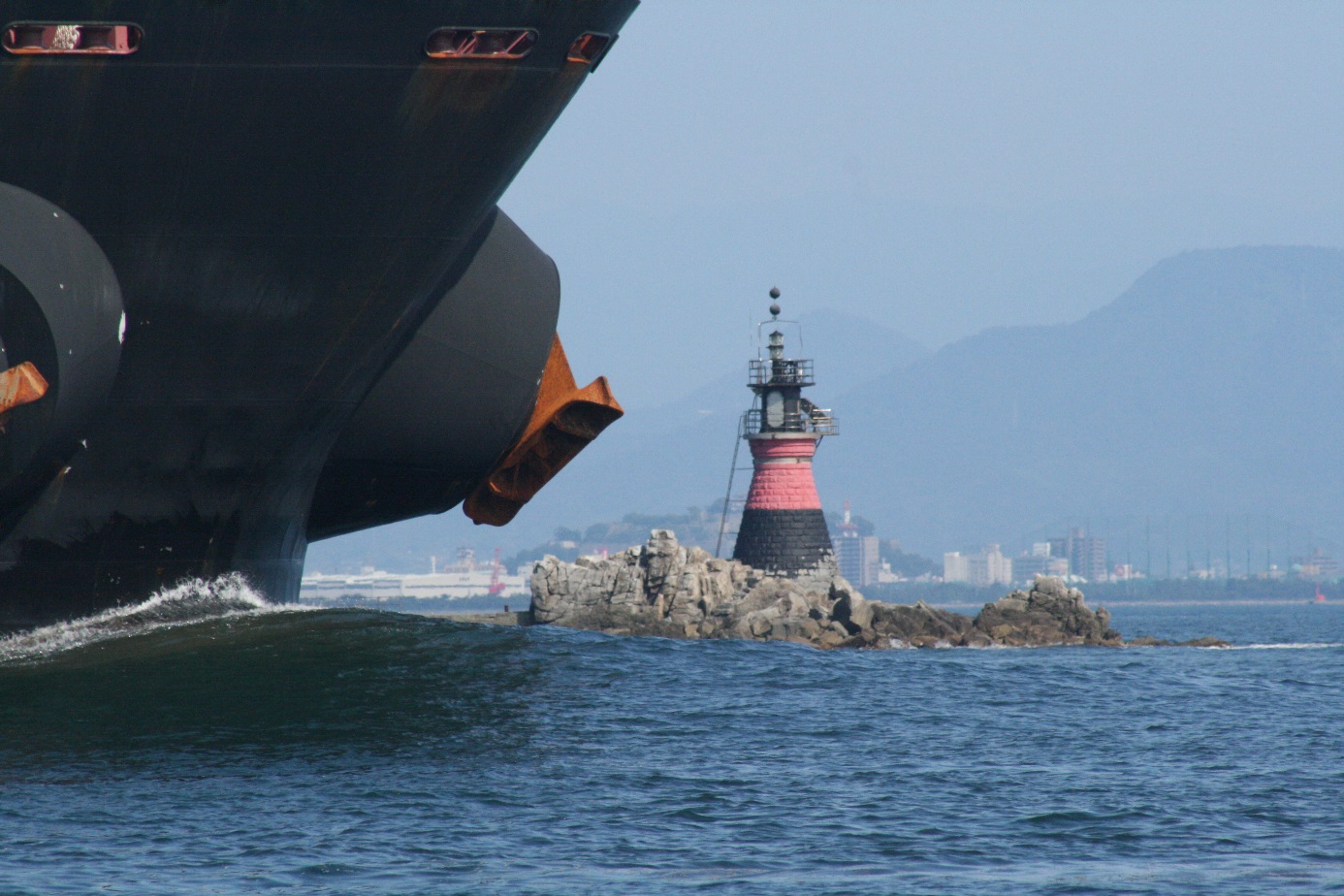
Bulbous Bow retrofit
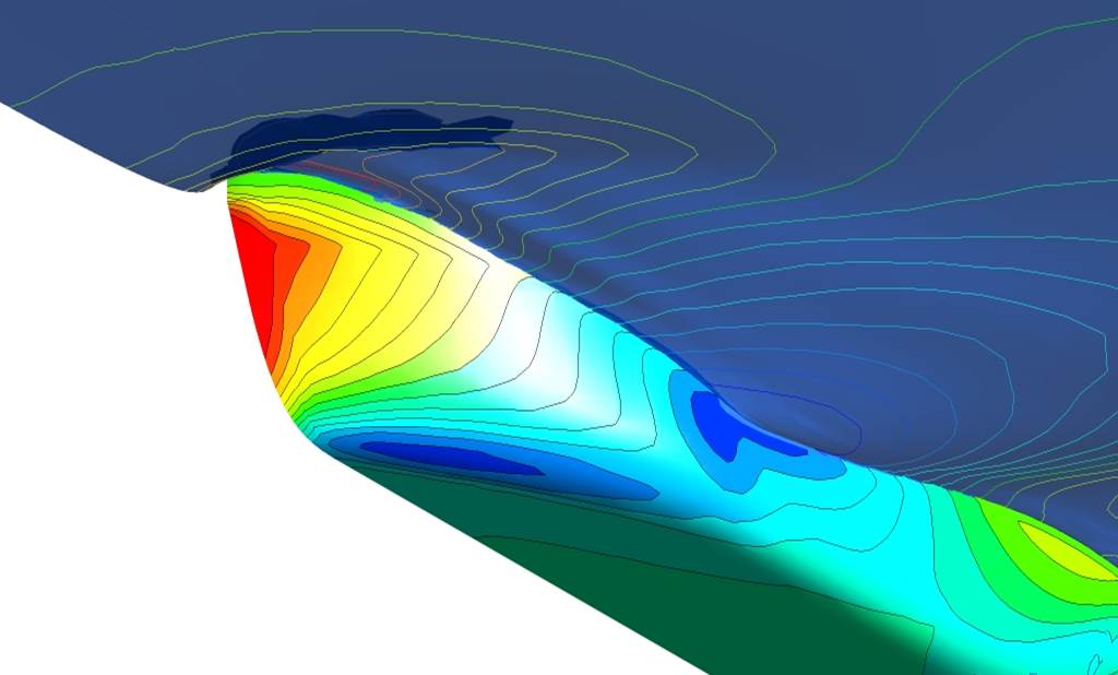
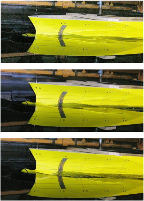
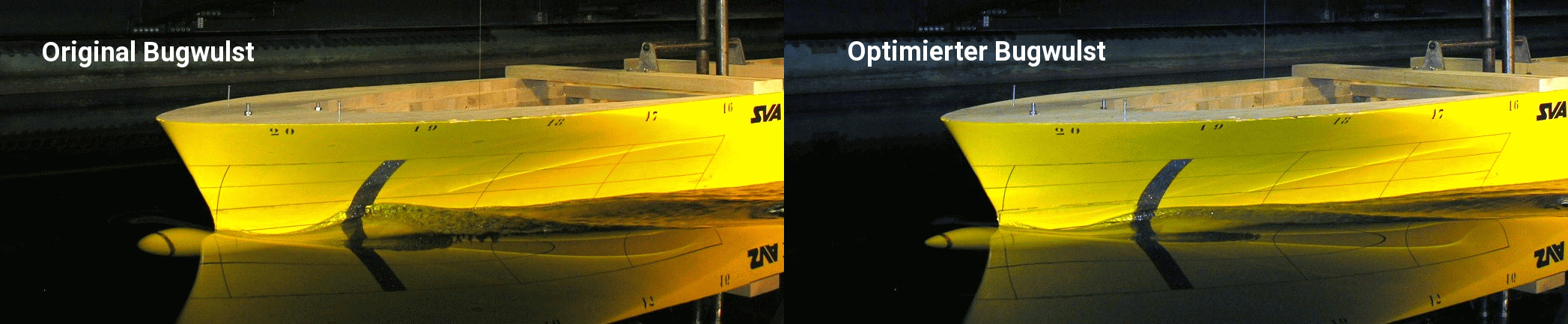
To minimize the cost of fuel, ships are now operated at lower speeds than a few years ago. Whereas with a 5-year-old container ship the Froude number is based on the design speed in a range from 0.21 to 0.25, these ships are now in a Froude number range of about 0.14 to 0.16. The speed reduction alone already results in significant fuel savings. In most cases, however, the bulbous bow is no longer optimal for the new, reduced speed range.
The original bulbous bow, which had been optimised for a Froude number of 0.21, but is running at a reduced Froude number of 0.145, produces an unfavourable wave system. The use of an optimised bulb for the new, reduced speed, in this case has led to a power saving of up to 8 %.
The SVA uses the FRIENDSHIP-Framework for bulbous bow optimisations. Structured and unstructured grid topologies are generated for CFD calculations based on the parametrically described geometry. The numerical calculations are performed with the ANSYS CFX program. In a multi-point optimisation, the ship lines are optimised with the required power and uniformity of the wake field as a target function.
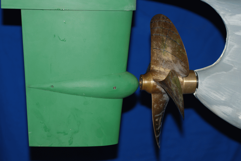
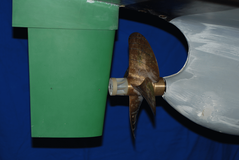
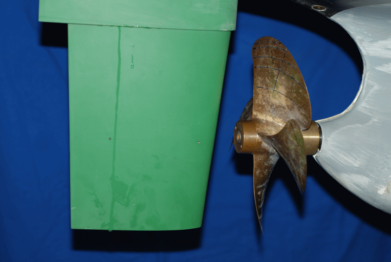
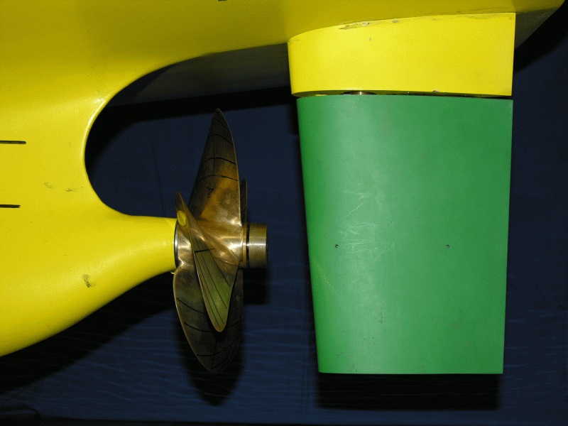
Propeller Re-Design
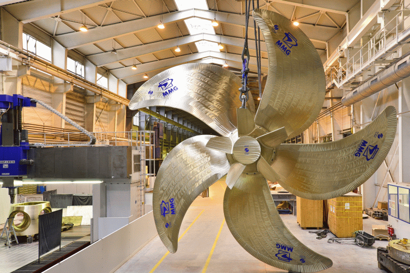
The lower thrust loading of the propeller in slow steaming results in greater freedom for propeller designs. Through increasing the propeller diameter, reducing the frequency of rotation, reducing the number of blades and the area ratio of the propeller, as well as the fine optimisation of the propeller blades, significant efficiency improvements can be achieved compared to the existing propeller, which was designed for higher vessel speeds. For large container ships, 6-bladed propellers are replaced with 5-bladed propellers with the transition to slow steaming. With a simultaneous increase of the propeller diameter by up to 5 % and reduction of area ratio by a third, power savings of 9 – 14 % can be demonstrated in experiments.
For the significantly slower bulk carriers, 4- and 3-bladed propellers are increasingly designed and investigated for both re-design projects as well as for the construction of new vessels. The area ratios of these propellers are in the range of AE/A0 = 0.35 to 0.45. Systematic investigations have shown that the 3-bladed propellers generate marginally higher pressure fluctuation amplitude in the first blade harmonics number. If the 3-bladed propeller is designed with a sufficient skew angle, the pressure fluctuation amplitudes of the higher blade number harmonics are in the range of propellers with a higher number of blades.

Context Related References / Research Projects
[1] Heinke, H.-J.; Lübke, L. O.: Maßnahmen zur Energieeinsparung, Schiff & Hafen, Nr. 10, 2014