Cavitation Tunnel
Main Parameters of the Sensors |
|||
| Parameter | R37 | R35X | |
| Components in x direction (x) | [N] | 800 | 500 |
| Components in y direction (y1, y2) | [N] | 800 | — |
| Components in z direction (z1, z2, z3) | [N] | 500 | — |
Main Parameters of the Dynamometers |
||||
| Parameter | J25 | H36 | R45 | |
| Propeller thrust | Tmax [N] | 3000 | 2000 | 400 |
| Propeller torque | Qmax [Nm] | 150 | 100 | 15 |
| Propeller speed | nmax [s-1] | 60 | 50 | 50 |
| Shaft angle | [°] | +15 bis -10 | ||
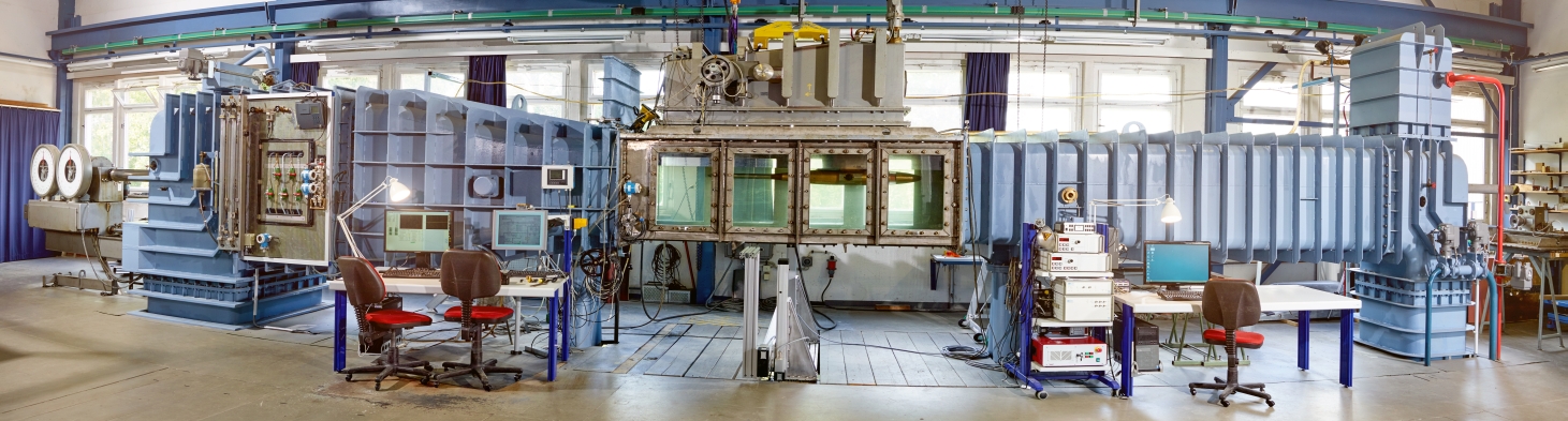
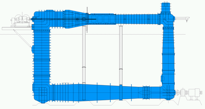
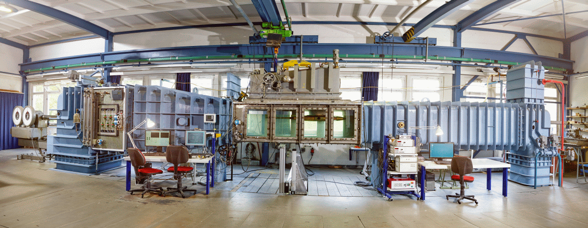
The SVA Potsdam operates the K15A cavitation tunnel from Kempf & Remmers. There are two measurement sections available. The length between the two vertical parts of the cavitation tunnel is 12 m, the height between the horizontal parts is 7 m. The impeller of the cavitation tunnel is powered by a 100 kW DC motor.
The cavitation tunnel has J25 and H36 dynamometers. Both dynamometers can be operated alone or together, so that tests with counter rotating and/or tandem propellers can be performed. In addition, the water- and pressure-tight R45 type inner drive dynamometer is available for special tests (i.e. overlapping propellers).
The velocity in the test section of the cavitation tunnel is determined from the pressure differential ahead of and behind the nozzle (Venturi principle). The pressure in the test section and the atmospheric pressure are also measured with pressure sensors.
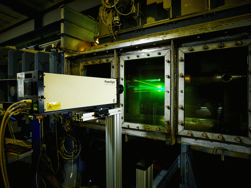
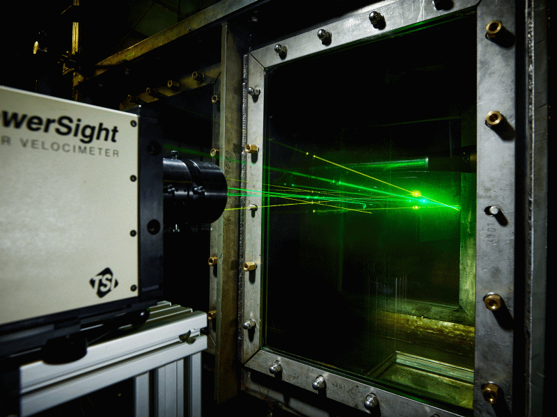
For the measurement of forces on profiles, lifting surfaces, nozzles and rudders, the R37 and R35x sensors are available. By default, local speeds are measured with a laser (Powersight LDV (TSI)). For the measurement of velocity fields, a PIV measurement system from TSI can also be used.
In the small test section, cavitation tests with propellers for fast ships, special tests such as measurements on profiles and wings, speed measurement with LDV or PIV, erosion tests and calibrations of speed measurement systems are predominantly performed.
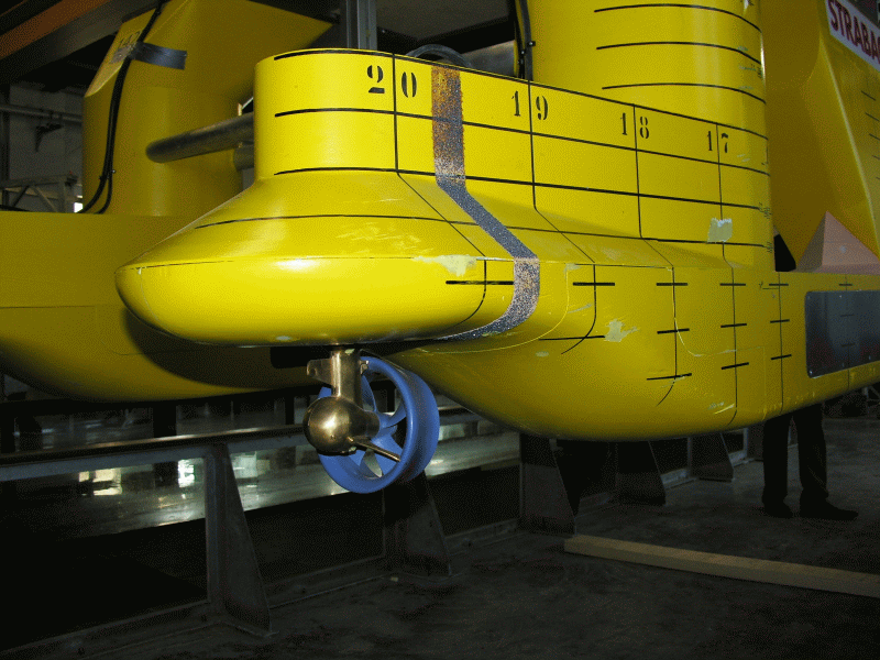
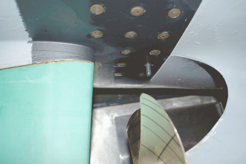
The investigation of the cavitation behaviour of propellers in the wake field of a vessel and the measurement of the propeller induced pressure fluctuations take place in the large measurement section of the cavitation tunnel. The simulation of the wake field, calculated for the full-scale Reynolds number, is made with a dummy model and additional screens [1], [2], [3], [4]. The H36 dynamometer is integrated in the dummy model. The dummy models are up to 2.60m long and geometrically similar to the ship in the stern area. Pressure sensors are arranged in the dummy model above the propeller. Standard in the SVA, the CFD calculated wake field of the full-scale model is simulated with a dummy model and additional screens.
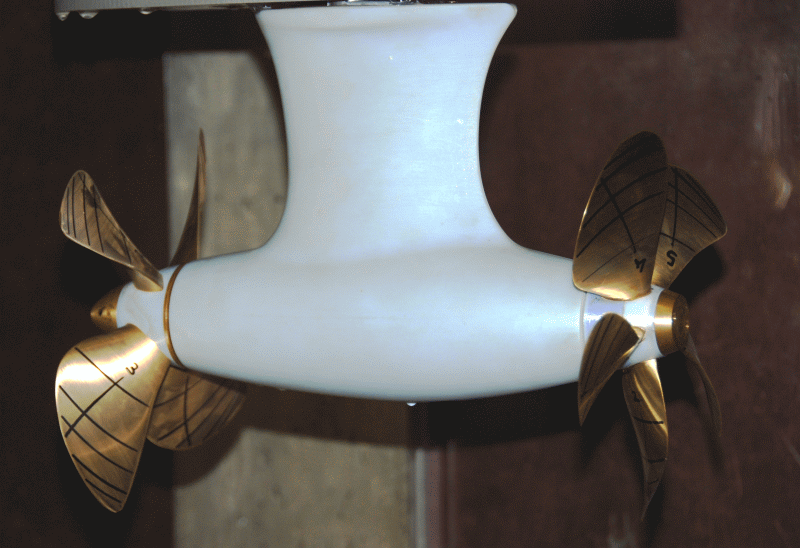
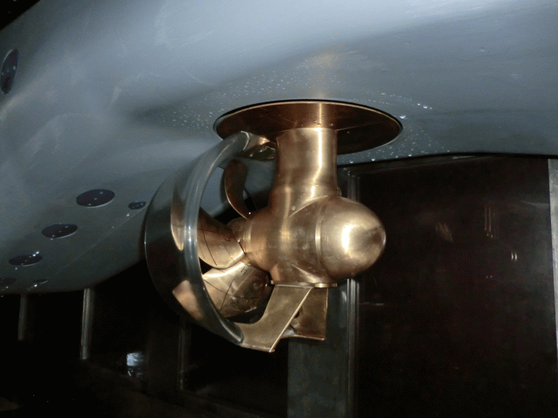
For the investigation of the cavitation behavior of thrusters, podded drives and Voith-Schneider propellers or steering propellers, special measurement systems have been developed. The same goes for power and torque measurements on individual blades of adjustable pitch propellers at cavitation similarity.
Please read more about the various tests and test objects in the Cavitation Tunnel here.
Technical Specifications of the Test Sections |
||
| Parameter | Test Section 1 | Test Section 2 |
| Measurement section length | 2600 mm | 2600 mm |
| Measurement section area | 600 mm x 600 mm | 850 mm x 850 mm |
| Contraction ratio of the nozzle | 5.96 : 1 | 2.93 : 1 |
| Maximum speed in the test section | 13 m/s | 7.5 m/s |
| Variation of the measurement section pressure | -970 mbar bis 1200 mbar | -950 mbar bis 1200 mbar |
Context Related References / Research Projects
[1] Selke, W., Heinke, H.-J.: Propelleruntersuchungen im Kavitationstunnel der Schiffbau-Versuchsanstalt Potsdam, Jahrbuch der STG, 84. Band, 1990
[2] Schmidt, D., Selke, W., Gerchev, G.: Comparative Joint Investigations in the Cavitation Tunnels of SVA and BSHC on the Prediction of Propeller-Induced Pressure Pulses, Schiffbauforschung 31 (1992) 1
[3] Heinke, H.-J.: The Influence of Test Parameters and Wake Field Simulation on the Cavitation and the Propeller Induced Pressure Fluctuations, Jahrbuch der Schiffbautechnischen Gesellschaft, 97. Band, 2003
[4] Kleinwächter, A., Hellwig-Rieck, K., Ebert, E., Kostbade, R., Heinke, H.-J., Damaschke, N. A.: PIV as a Novel Full-Scale Measurement Technique in Cavitation Research, Fourth International Symposium on Marine Propulsors, smp’15, Austin, Texas, USA, 2015
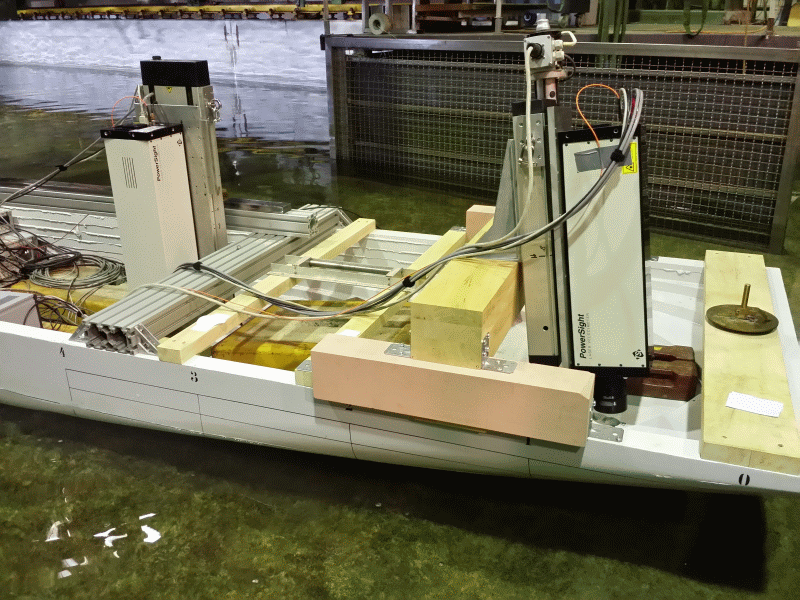
Velocity fields can be measured nearly instantaneously, with high accuracy and high spatial and temporal resolution by means of a LDV-system. Laser measurements are performed routinely in the SVA since 1985. For this application SVA provides compact probes with integrated solid-state laser (PowerSight probe from TSI). The probes are portable and flexible in use. In the cavitation tunnel, a 2D LDV is mainly used. In the towing tank and for mobile tasks primarily a 1D system is applied. Both compact probes can be combined into a 3D measuring system. When a submersible probe is required, a waterproof 2D probe (83 mm diameter) can be coupled to the laser module via optical fibers.
Technical specifications |
| 2D PowerSight probe with 500 mW DPSS laser (561 nm and 531 nm) and 3 channel photomultiplier and signal processor |
| 1D PowerSight probe with 200 mW DPSS laser 553 nm with 1 channel photomultiplier and signal processor |
| Use as 3D LDV possible |
| Beam spacing 50mm, lenses 250, 350, 500, 600 mm, minimum measurement volume length 0.7 mm, diameter 62 microns |
| Computer-controlled 3D traversing |
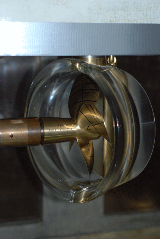
Ducted Propellers
Kempf & Remmers dynamometers are used for propeller drives. The forces at the nozzle are measured with Kempf & Remmers single and multi-component balances that are coupled to the dynamometers.
Main Paramters Dynamometer/Balances for Ducted Propellers |
|||||||
| FK1/R35I | H29/R35X | H39/R35X | H39/R37 | H36/R35X | J25/R37 | ||
| Thrust Tmax | [N] | * | 400 | 1000 | 1000 | 2000 | 3000 |
| Torque Qmax | [Nm] | * | 15 | 50 | 50 | 100 | 150 |
| Nozzle Thrust TDmax | [N] | 200 | 500 | 500 | 800 | 500 | 800 |
| * Using Interior Drive Dynamometer | |||||||
Contra-rotating Propeller
The SVA has the Kempf & Remmers contra-rotation dynamometer R40 for open water and propulsion testing. Open water tests with contra-rotating propellers can also be performed via the coupling of the H29 and H39 dynamometers in the towing tank. For the investigation of contra-rotating propellers, the K15A cavitation tunnel was equipped with J25 and H36 dynamometers from Kempf & Remmers. The dynamometers can be arranged in the measurement section so that measurements with contra-rotating propellers are possible at different distances.
Main Paramaters Dynamometer/Balances for Contra-rotating Propellers |
||||
| FK4/R40/R35I | H29/H39/R35X | J25/H36/R35X | ||
| Thrust Tmax1 | [N] | 150 | 400 | 3000 |
| Thrust Tmax2 | [N] | 150 | 1000 | 2000 |
| Torque Qmax1 | [Nm] | 6 | 15 | 150 |
| Torque Qmax2 | [Nm] | 6 | 50 | 100 |
| Housing Resistance TPodmax | [N] | 200 | 500 | 500 |
Thrusters and Podded Drives
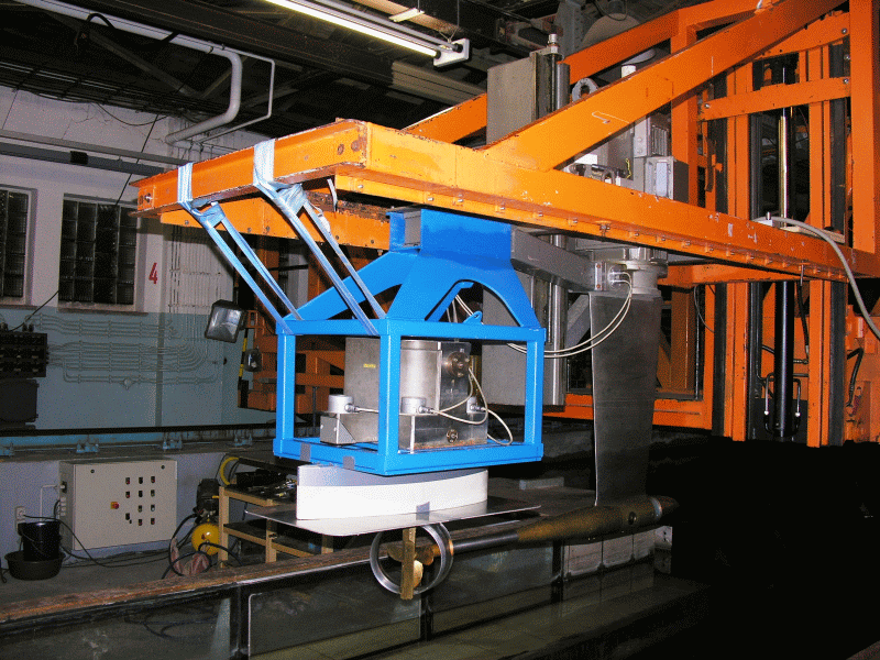
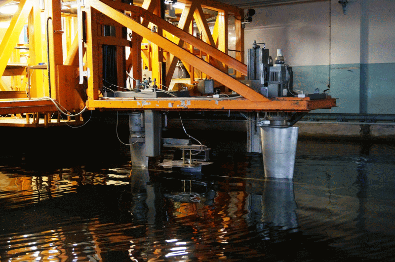
Model tests with azimuthing thrusters and podded drives are a focus of the work of the SVA. For the realisation of measurement tasks in open water, cavitation, propulsion and manoeuvring, different propulsion and measuring systems have been developed by the SVA. The system forces of the thruster and podded drive are measured with 3- or 6-component balances.
Main Parameters Balances for SVA Thruster Dynamometer |
||||||
| R37SR1/SR2 | R37SR3/SR4 | R37 | R200 | |||
| Forces | Fx1 = Fy1 = Fy2 | [N] | 200 | 500 | 800 | 1000 |
| Fz1 = Fz1 = Fz2 | [N] | – | 1000 | 500 | 2000 | |
| Turntable | Fx | [N] | 100 | 100 | manual | 5000 |
| Fy | [N] | 100 | 100 | 3400 | ||
| Fz | [N] | 600 | 600 | 5000 | ||
| Mx1 = My | [Nm] | – | – | 500 | ||
| Mz | [Nm] | 15 | 15 | 60 | ||
The drive of the propeller and the measurement of the forces and moments on the propeller are carried out with SVA thruster dynamometers. Thruster dynamometers are available at the SVA for tests with thrusters or podded drives with pull, push, twin and contra-rotating propellers.
Main Parameters SVA Thruster Dynamometer for Single Propeller Systems |
||||
| Z65/1 – /4 | Z200 | Z600/4, Z600/6 | ||
| Thrust Tmax | [N] | 50 | 200 | 600 |
| Torque Qmax | [Nm] | 1 | 7 | 20 |
| Transmission | * | 1.615:1 | 2:1 | |
| Housing Resistance TPodmax | [N] | 200 | 500 | 500 |
| Total Torque QGmax | [Nm] | 1 | 2.4 | 17 |
| * Drive with an electric motor in the housing | ||||
Main Parameters SVA Thruster Dynamometer for Double Propeller Systems |
|||||
| TP200/1…/2 | TP400/1…/2 | CRP400 | CRP600 | ||
| Thrust Tmax | [N] | 200 | 400 | 400 | 600 |
| Torque Qmax | [Nm] | 7 | 20 | 20 | 20 |
| Transmission | 1.1 | 2.1 | 2:1 | 2:1 | |
| Total Torque QGmax | [Nm] | 6 | 17 | 17 | 17 |
Context Related References/Research Themes
[1] Gutsche, F.: Düsenpropeller in Theorie und Experiment, Jahrbuch der STG, Bd.53, 1959
[2] Schroeder, G.: Wirkungsgrad von Düsenpropellern mit unterschiedlicher Düsen- und Propellerform, Schiffbautechnik, 1967
[3] Heinke, H.-J.; Philipp, O.: Development of a skew blade shape for ducted controllable pitch propeller systems, Proceedings, PROPCAV’95, Newcastle, 1995
[4] Schulze, R.; Manke, H.: Propellersysteme mit Ostdüsen“, HANSA, 137, 2, 2000
[5] Schmidt, D.: Propulsionsuntersuchungen mit Einzelpropeller und Gegenlaufpropeller am Modell eines Containerschiffes, Schiffbauforschung 14 1/2/1975
[6] Heinke, H.-J.: Azimuthing propulsion – Experiences of SVA, 6. SVA – Forum „Azimuthing Propulsion – new challenges and chances“, Potsdam, 1998, Schiffbauforschung, 38. Jahrgang (1999) Heft Nr. 1
[7] Kaul, S.; Heinke, H.-J.; Abdel-Maksoud, M.: Hydrodynamische Optimierung von Podded Drives und aktuelle Anwendungen in der Großausführung, 54. Sitzung des FA „Schiffshydrodynamik“ der STG, Hamburg, September 2000
[8] Heinke, H.-J.: Investigations about the forces and moments at podded drives, First International Conference on Technological Advances in Podded Propulsion, Newcastle, UK, April 2004
[9] Heinke, H.-J.: Hydrodynamische Untersuchungen für einen Podded Drive mit HTS-Synchronmaschine, Statustagung Schifffahrt und Meerestechnik, Bundesministerium für Wirtschaft und Technologie, 03. Dezember 2009, Rostock-Warnemünde

The pressure pulses induced by the propeller are measured with absolute pressure sensors. Typically, an array of sensors, 11 to 16, above the propeller is arranged.
If evidence of higher frequency levels at the hull is of interest, hydrophones are arranged in close range of the model propeller in the outer skin of the model. To determine the noise spectra induced by the propeller, hydrophones are placed on the windows or directly inside the test section of the cavitation tunnel.
For the analysis and comparison of acoustically optimised propellers, direct measurement of vibrations is carried out on the propeller. A high frequency acoustic emission sensor is installed with pre-amplifier and transmitter in a special hub cap. The sampling rate is 44100 Hz.
Technical Specifications |
|
| Brand | Photron |
| Sensor Type | CMOS |
| Max. Resolution | 1024 x 1024 px, 2000 fps |
| Max. Frame Rate | 120.000 fps |
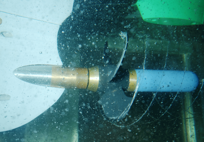
An observation of cavitation on rotating propellers is consequently possible. The advantage compared to the conventional stroboscopic technique lies in the possibility of an evaluation of the cavitation dynamics on the basis of video recordings and thus also their influence on the erosion. The main place of use for the high speed camera system is the cavitation tunnel.
Context Related References / Research Projects
[1] Heinke, H.-J.: High-Speed Camera Observations of the Cavitation at VSP Blades, 2th Symposium on Voith Schneider Technology , Heidenheim, 6. June 2008
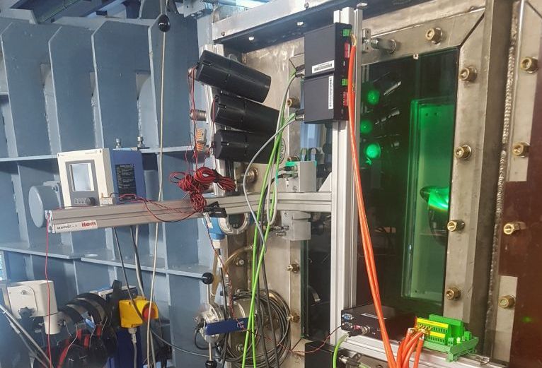
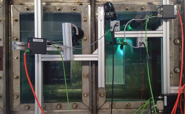
In this context, the Optical Cavitation Inspection System (OCIS) was integrated into SVA’s cavitation research as part of the “R&D Funding Program for Non-Profit External Industrial Research Institutions – Innovation Competence (INNO-KOM)” (Reg. No. IZ 49IZ210009). OCIS includes components such as the KED-Photonics® Nuclei Sizer 300 (based on HDNC technology) for measuring cavitation nuclei concentration, and a synchronized multi-camera and LED lighting system (KED-Photonics® Cavitation Imager 2.1).
Using OCIS, cavitation phenomena are synchronously recorded with multiple cameras and subsequently reconstructed in three dimensions. Image processing techniques are employed to determine the spatial extent of cavitation and the probability of its occurrence. Data on the distribution of nuclei in the water, as well as objective statistics on observed cavitation, form the basis for correlation analyses, which are critical for evaluating cavitation experiments and conducting complex cavitation simulations.
The measurement system was developed through continuous research and development within the collaborative R&D projects KonKav and HiOcav, funded by the BMWi (Federal Ministry for Economic Affairs and Energy). These efforts targeted key challenges in current cavitation research, such as determining the nuclei spectrum in water and resolving the temporal and spatial extent of cavitation. SVA actively participated in these projects, contributed significant foundational work, and gained extensive experience in the application and use of the technology.
Friction Measurement Test Stand
Please read more about our friction measurement test stand here.