Computational Fluid Dynamics (CFD)
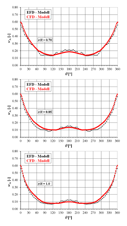
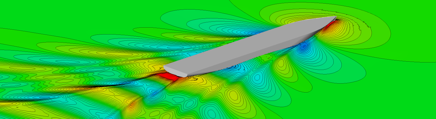
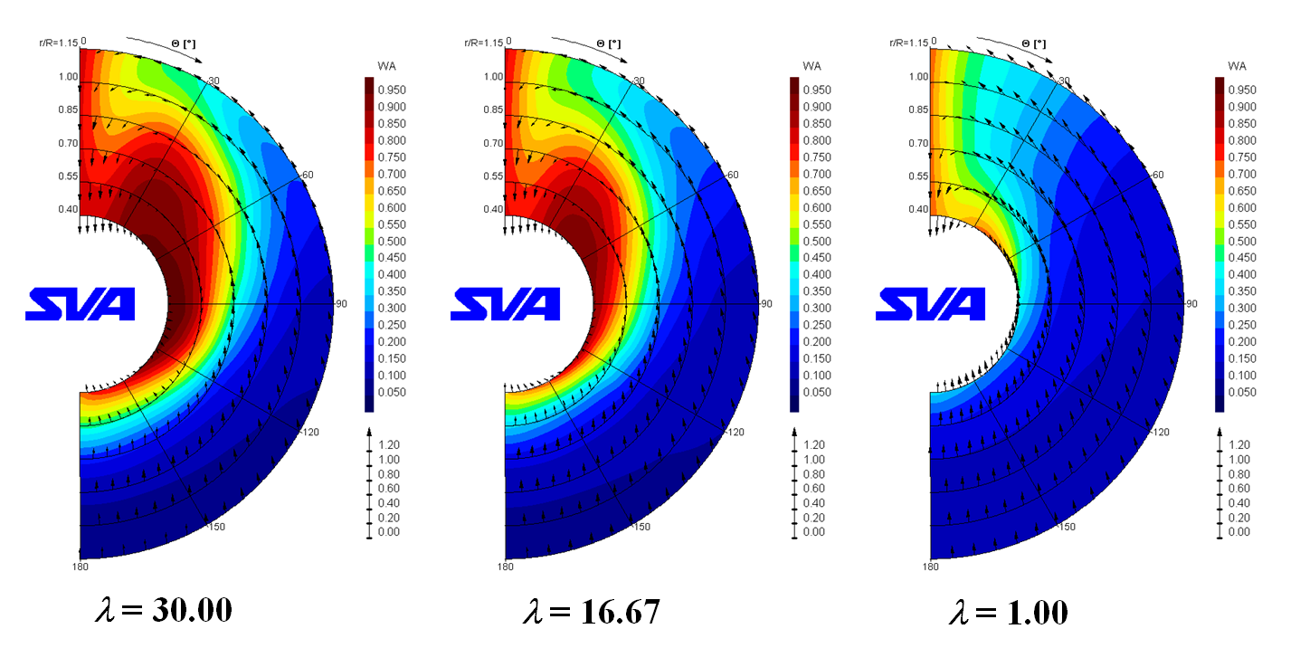
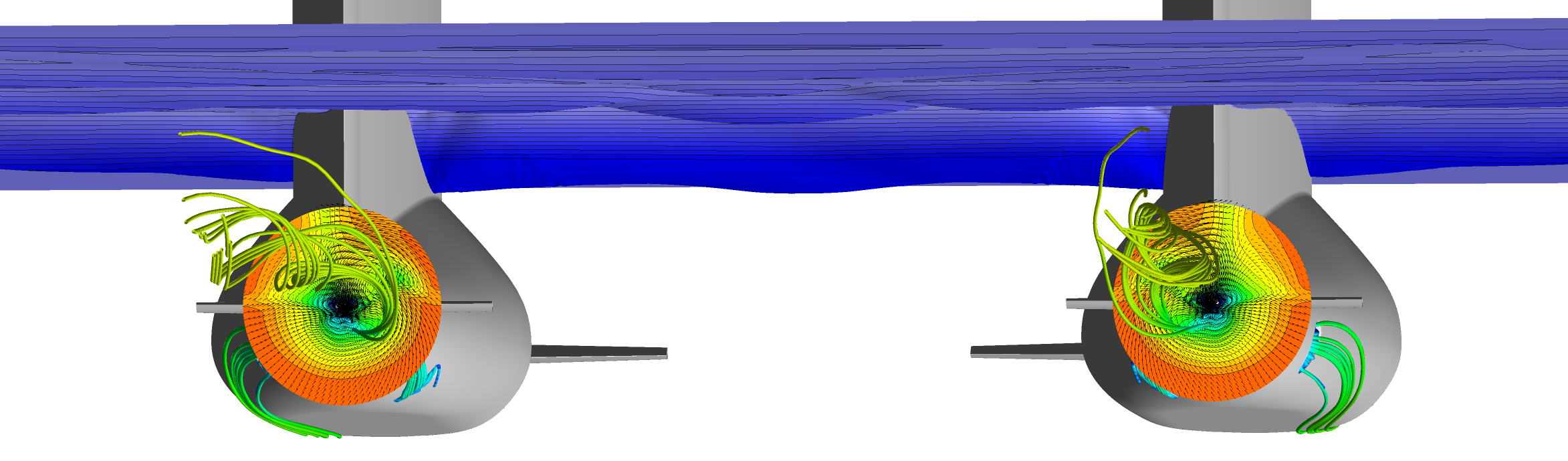
The wake fields between model and full-scale show differences because of the underlying physics. In model-scale the boundary layer is thicker relative to full-scale and the bilge vortex more pronounced. This results in differences in the inflow to the propeller between model and ship, which should be considered when designing the propeller. Through the use of numerical methods, the wake field can be calculated for both the model and the ship. Thus it is possible, already while designing the ship lines, to evaluate the wake field and the influence of geometry modifications or appendages. Further, the wake field can be made available for propeller design.
The numerical simulations offer the following advantages:
- Calculation of the wake field in the preliminary design stage
- Calculation of the wake field for the Reynolds number of the vessel
- Evaluation of the velocity components of the wake for any radius and angular increments
- Visualising the inflow and presentation of the causes (for example, separations) for potential irregularities
Context Related References / Research Projects
[1] Abdel-Maksoud, M., Lübke, L.: Berechnung des Nachstromfeldes der Großausführung, 97. Hauptversammlung der Schiffbautechnischen Gesellschaft, Hamburg, 20.-22.11.2002
[2] Lübke, L.: Calculation of the Wake Field in Model and Full-scale, NAV 2003, International Conference on Ship and Shipping Research, Palermo Italy, 24.-27. June 2003
[3] Lübke, L.: Calculation of the Wake Field in Model and Full-scale, CFX Conference 2003, Garmisch-Partenkirchen, 04. – 06. November 2003
[4] Lübke, L.: Validation of CFD Results behind the Working Propeller of a Ship Model, 7th Numerical Towing Tank Symposium, Hamburg, 03.-05. October 2004
[5] Lübke, L., Mach, K.-P.: LDV Measurements in the Wake of the Propelled KCS Model and its Use to Validate CFD Calculations, 25th Symposium on Naval Hydrodynamics, St. John’s, Newfoundland and Labrador, Canada, 08-13 August 2004
[6] Lübke, L.: Berechnung des effektiven Nachstromfeldes der Großausführung, 11. SVA-Forum, Potsdam, 09.11.2004
[7] Lübke, L.: Formoptimierung unter Berücksichtigung der Charakteristik des Nachstromfeldes, 4. SVA Forschungsforum „Theoria cum praxi“, Potsdam, 27.01.2011
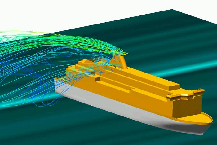
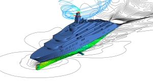
Along with resistance and stability considerations resulting from wind loads, the focus of aerodynamic investigations of the hull above water is also on the problems of exhaust and intake from ventilation and air conditioning systems and the analysis of exhaust gas concentrations. The latter applies primarily to yachts and passenger ships, where comfort aspects are an important design criterion.
Due to the complex geometry of superstructures or masts, turbulence and recirculation zones can arise which can be examined in terms of gas distribution. To process such inquiries, numerical methods can offer possible solutions in order to verify structural aspects and to carry out calculations on variants.
Through simulation the following aspects may be considered:
- Calculation of wind, exhaust gas, intake and exhaust flow, and detection of mutual interactions
- Detailed visualisation of the flow and fluid concentrations, i.e. the exhaust gas
- Calculation of the flow around the whole ship (not linked to specific measurement positions)
- Temperature distribution for the detection of “hotspots”
- Accounting for the wind profile
- Calculation for full-scale version
Context Related References / Research Projects
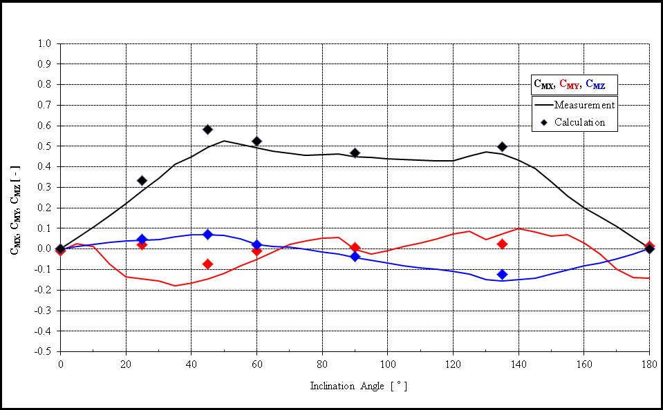
[1] Blendermann, W., Hellwig-Rieck, K., Schuckert, E.: Wind Loads on a Passenger/Car Ferry by CFD Computations and Wind Tunnel Tests, Ship Technology Research, Vol. 58, No. 2 (2011)
For this optimisation, among other things, various parametric models of the “CAESES” software are used. The optimisation is done on the basis of viscous CFD calculations, since these are considerably more reliable in optimising than the potential theory method. The savings benefits are generally considerable and give, over the life of the vessel, a significant increase of the “return on investment”. Classical optimisation tasks are the optimisation of bows, bulbous bows, and sterns. While on new designs an optimal concept is at once available, in the area of retrofitting, especially a bulbous bow, optimisation makes sense. Generally, this is done for the customer’s predefined mission profile fully parametrically. The example shows the development of the drag resistance of a ship geometry depending on the variation of the bulbous bow.
As a secondary condition of minimum resistance or propeller thrust, optimisation of the flow into a propeller (homogeneity of the wake) can be considered.
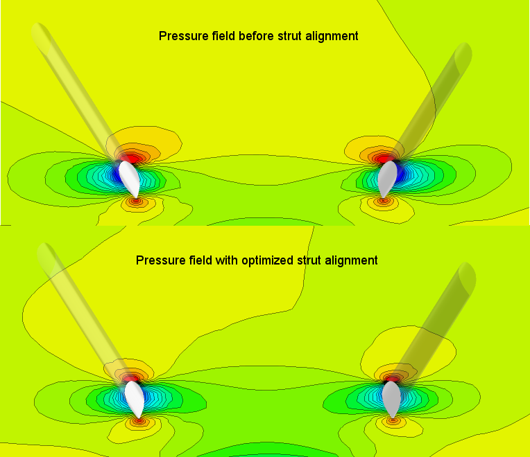
Propeller struts, stabiliser fins and other appendages can make a significant contribution to the ship’s resistance. Through the optimised shape and alignment of the appendages, the resistance and the loading of the attachments are minimised. Accordingly the propeller wash becomes homogeneous, improving the quality and efficiency of propulsion and contributing to the reduction of vibration and noise.
Context Related References / Research Projects
[1] Lübke, L.: Optimierung von Schiffsanhängen an großen Yachten, Fachseminar Numerische Simulation und Optimierung, Berlin, 24.05.2007
[2] Lübke, L.: Formoptimierung unter Berücksichtigung der Charakteristik des Nachstromfeldes, Forschungsthema, 04/2007 – 12/2009
[3] Lübke, L.: CFD in Ship Design, STG Sprechtag, 25.09.09 Hamburg
[4] Lübke, L.: CFD in Ship Design, ANSYS Conference & 32nd CADFEM Users Meeting 2014, Nürnberg, June 4-6, 2014
The use of numerical methods offers many opportunities to examine ships at sea. The SVA can use the program system UTHLANDE or RANSE Method depending on the application. UTHLANDE provides the ability to perform seaway calculations based on linear and non-linear strip method. Using this method, monohulls and catamarans can be studied over a wide range of applications and short- and long-term statistics can be calculated. For special cases or the simulation of non-linear applications, RANSE Method (ANSYS Fluent) is used.
With numerical calculations, issues can be examined in terms of added resistance or the acceleration and motion behavior of ships. Added resistance at sea is an essential aspect in order to determine power requirements and operating costs of vessels correctly. The motion behaviour at sea, however, is an essential aspect of comfort and determines the operating limits of ships.
The numerical seaway simulations with RANSE procedures include the following applications:
- Seaway from any direction, stationary and in motion
- Calculation of regular and irregular sea states, with the focus on the calculation of regular seaway
- Determination of the added resistance
- Determination of accelerations
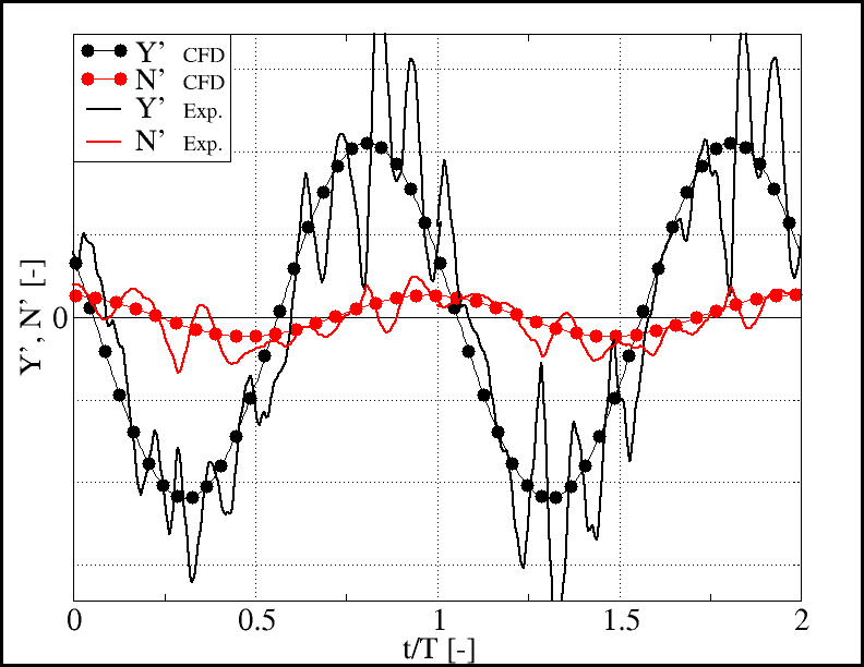
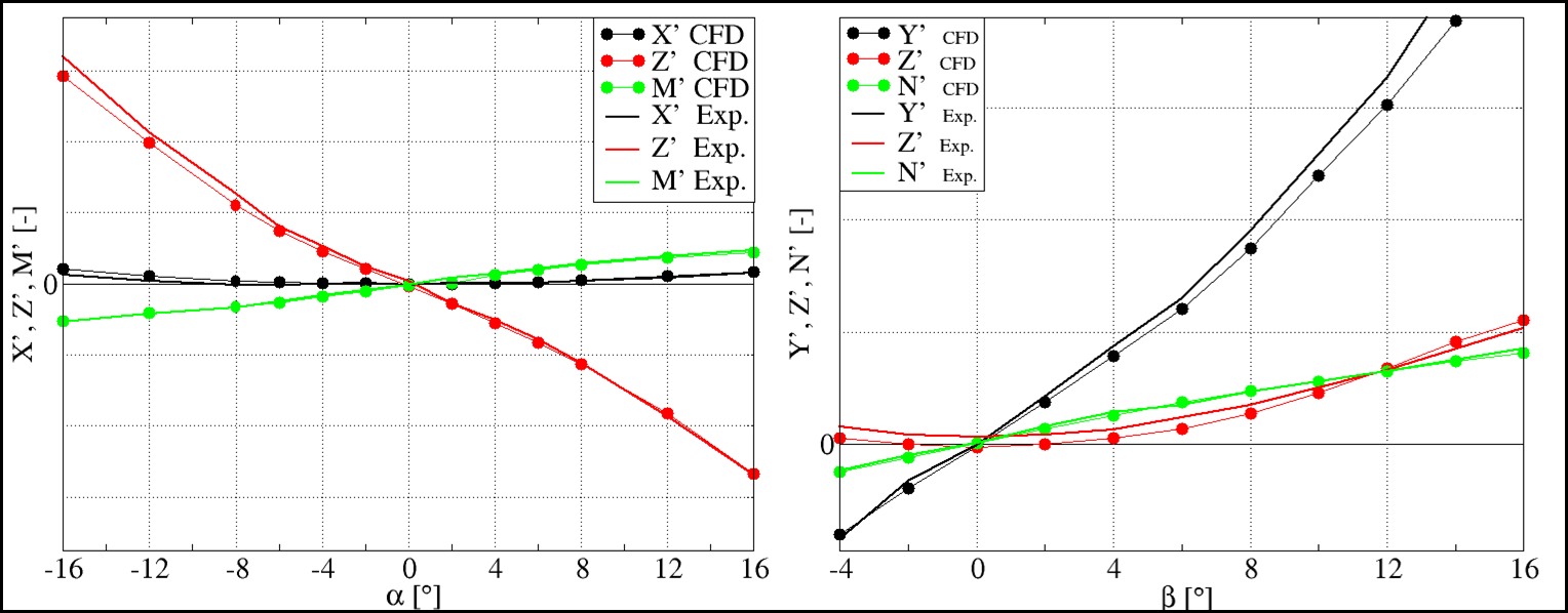
Numerical simulations allow to:
- Simulate manoeuvring behaviour in model and full-scale
- Simulation of static and dynamic tests
- Visualisation of flow, detection of separating flow
- Design of control elements such as rudders, thrusters, etc.
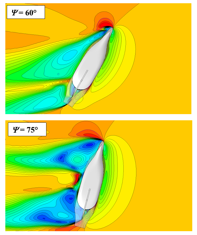
The rudder is by far the most frequently used control element; it operates in the wash of the propeller. Below, the pressure distribution on the rudder for a rudder angle of δR = 20° with a rotating propeller is shown.
Context Related References / Research Projects
[1] Lübke, L.: Investigation of a Semi-Balanced Rudder, 10th Numerical Towing Tank Symposium, Hamburg, 24.09.2007
[2] Lübke, L.: Investigation of a Semi-Balanced Rudder, 14. SVA Forum, Potsdam, 07.11.2007
[3] Lübke, L.: Investigation of a Semi-Balanced Rudder, ANSYS Conference & 25th CADFEM Users Meeting 2007, Dresden, 21. – 23.11.2007
[4] Lübke, L.: Numerische und experimentelle Untersuchungen an einem Halbschweberuder, STG-Sprechtag, Verbesserung der Propulsions- und Manövriereigenschaften von Schiffen, Papenburg, 18.09.2008
[5] Lübke, L.: Numerische PMM-Tests für Unterwasserfahrzeuge, ANSYS Seminar, Simulationswerkzeuge für die Marine und Offshore Industrie, Hamburg, 05.11.2008
[6] El Moctar, O., Brehm, A., Lübke, L.: Hydrodynamische und strukturmechanische Untersuchung von Rudern großer, schneller Schiffe (XXL-Ruder), PTJ Statustagung, Warnemünde, 11.12.2008
[7] Lübke, L.: Numerische und experimentelle Untersuchungen der effektiven Ruderzuströmung beim Manövrieren, 2. SVA Forschungsforum „Theoria cum praxi“, Potsdam, 29.01.2009
[8] Lübke, L.: Manoeuvering Simulations of Underwater Vehicles, 12th Numerical Towing Tank Symposium, Cortona Italy, 04.-06.10.2009
[9] Lübke, L.: Investigation of a Semi-balanced Rudder, Ship Technology Research, Vol. 56, No. 2, 2009
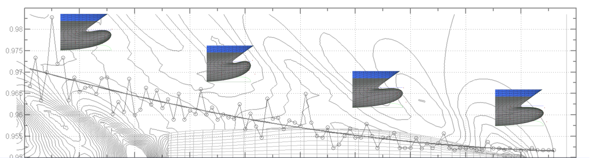
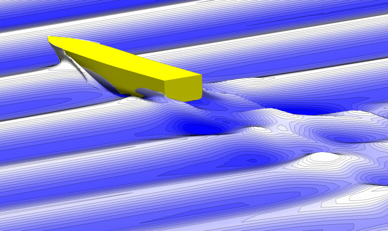
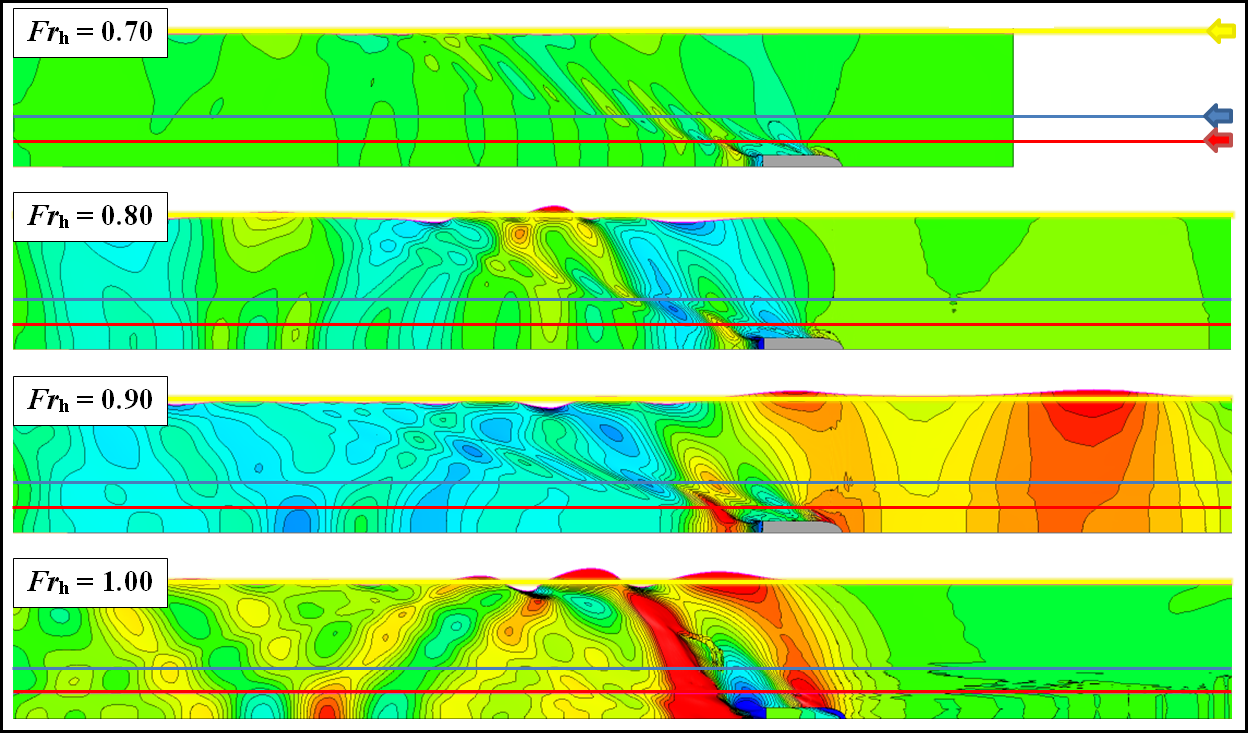
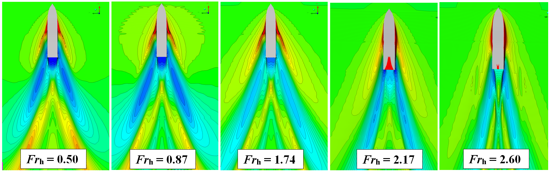
Shallow water has a significant influence on the handling of ships. The most obvious effect is the changing shape of waves in shallow water. Due to the different wave propagation and wave group velocities of deep and shallow water at the same wave length, the interaction between the different wave systems of a ship changes. This is manifested, among other things, through strong changes in KELVIN angle.
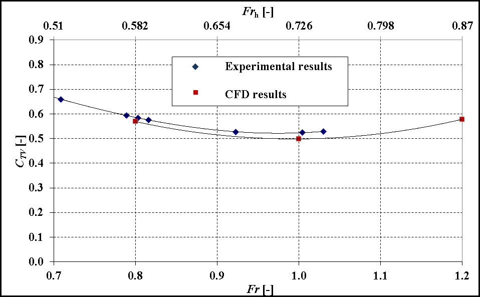
To illustrate the shallow water effects the Froude depth number is generally used; wherein the driving regimes are subvided in a subcritical (Frh < 0.9), critical (0.9 < Frh < 1.1) and a supercritical (Frh > 1.1) ranges. Normally, ships operate in the subcritical range. For critical Froude depth numbers, a strong increase in resistance and a large change in the dynamic flotation position can be expected depending on the ship type since, in this region, the transverse waves move at the speed of the vessel. As a special case, soliton waves can occur in this area. In the case of supercritical Froude depth number, the ship is faster than the maximum wave speed and the transverse waves disappear in the secondary wave system.
Numerical methods have extensive applications in the calculations of shallow water effects.
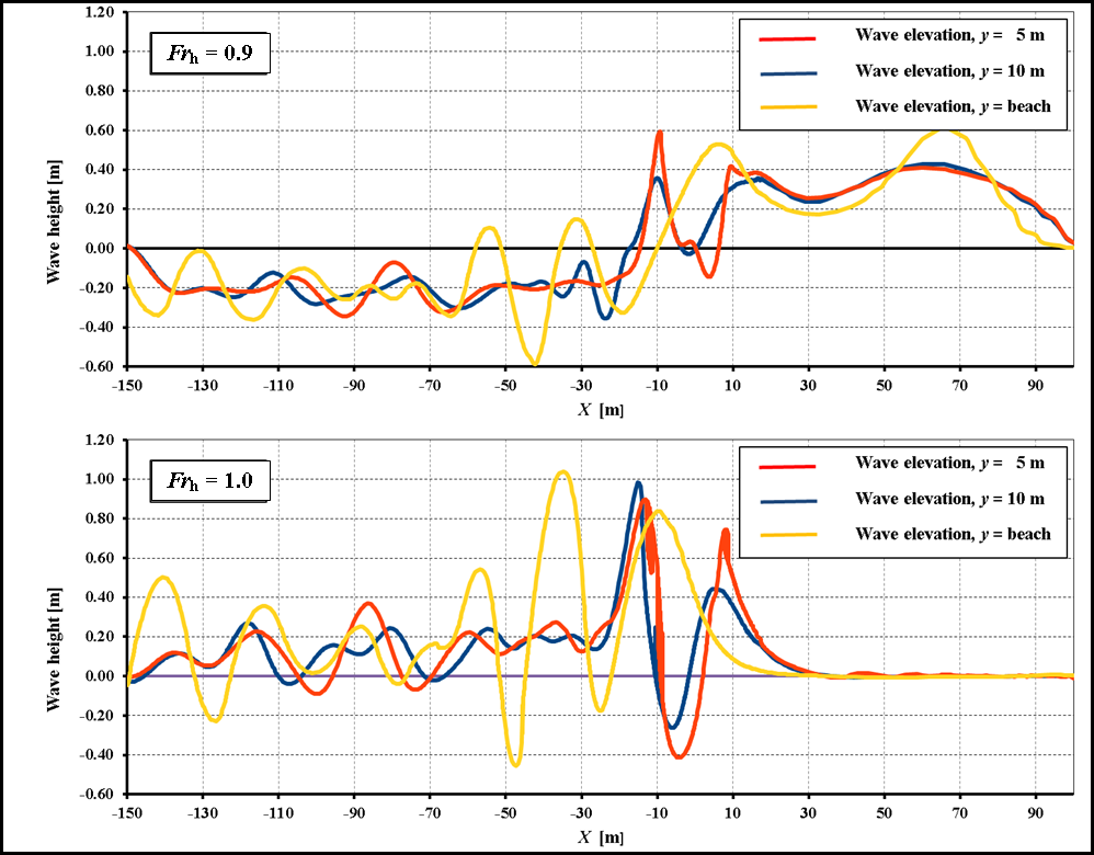
- Calculation of the resistance and the flotation position at varying depths, velocities and ground topologies
- Calculation of waves / wave heights on banks and shores.
The SVA uses ANSYS CFD for this.
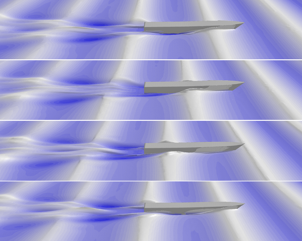
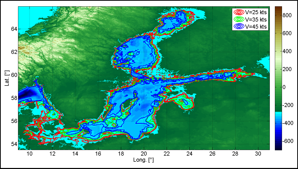
Fast moving ships are more affected by shallow water effects than slow moving ships. The areas of the Baltic Sea are represented in the image below for three different speeds where the vessel would be running in a critical Froude depth number (0.9 <Frh<1.1) speed range. Near the coast the boat is moving in supercritical range, further out on the Baltic Sea in the subcritical Froude depth number speed range.
Context Related References / Research Projects
[1] Nietzschmann, T.: Untersuchungen zum Widerstandsverhalten von schnellen Schiffen bei veränderter Bodentopologie, 6. SVA-Forschungsforum „Theoria cum praxi“, Potsdam, 31.01.2013
[2] Lübke, L.: Fast Ship Hydrodynamics on Shallow Water, 8th International Conference on High-Performance Marine Vehicles (HIPER), Duisburg 27. – 28.09.2012