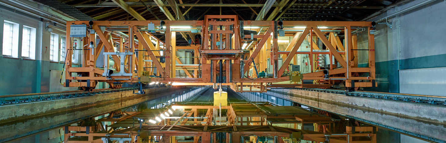
Towing Tank
At the front of the tank there is a wave generator which can produce regular and irregular waves and also wave packets up to a wave height of 0.30 m. At the back, the towing tank ends in a beach as a wave absorber.
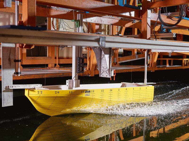
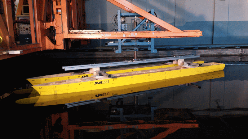
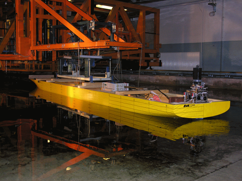
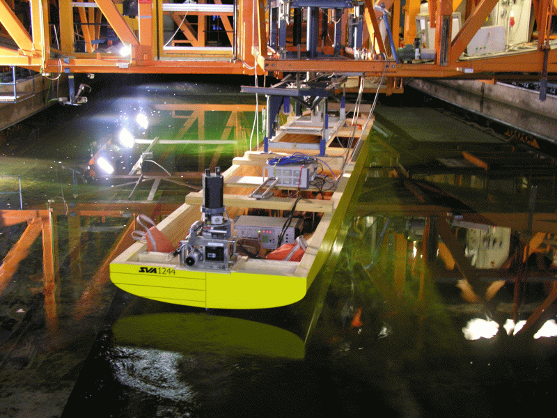
In the towing tank, free running tests are carried out with propellers and propulsion systems as well as resistance and propulsion tests, wake field measurements and paint flow tests. Additional elements of the testing spectrum include maneuvering, seakeeping tests and experiments with submersibles.
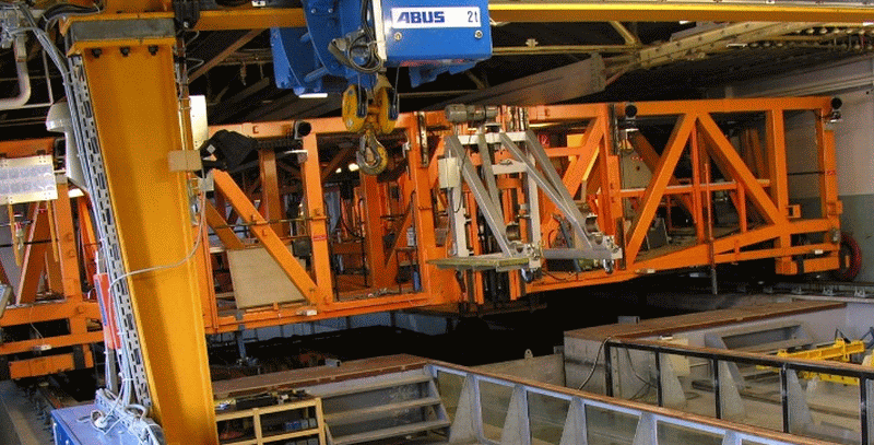
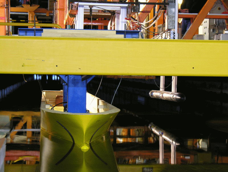
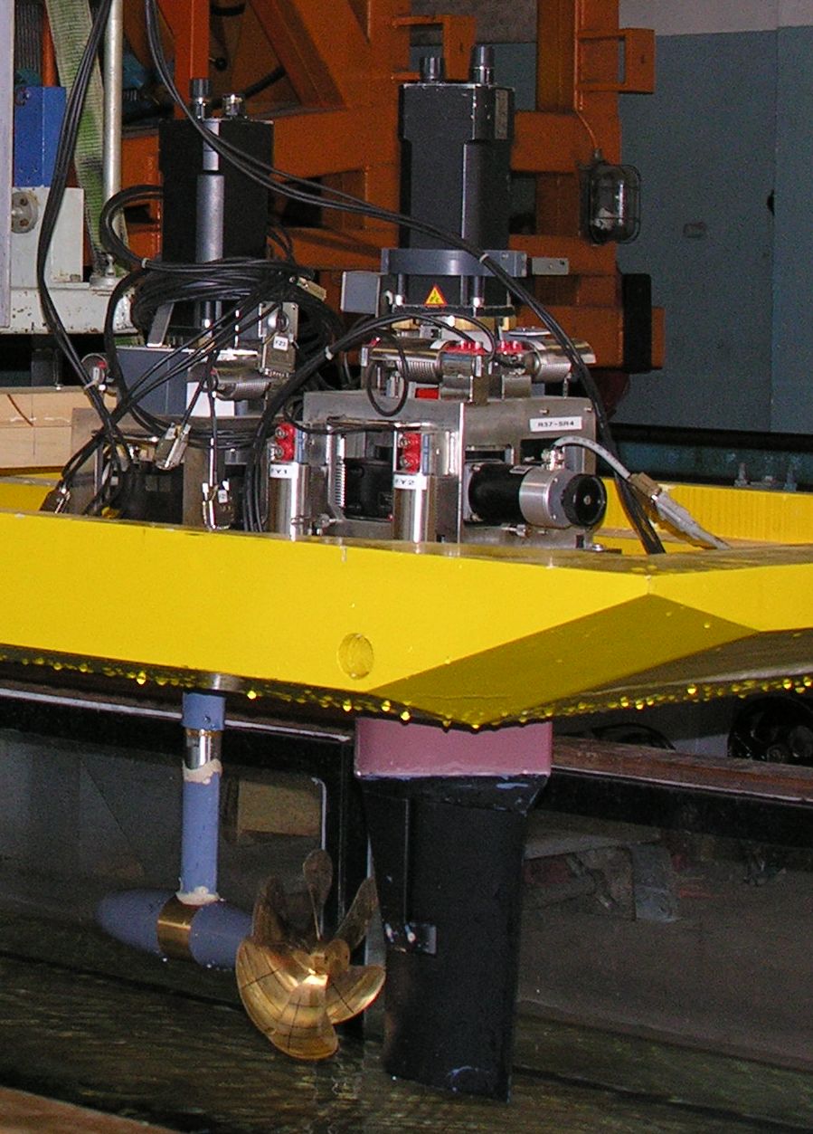
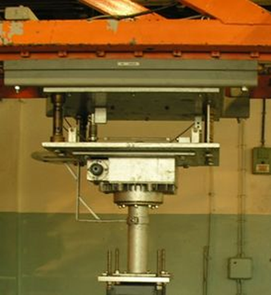
The towing carriage is provided with a flexible carrier system that can accommodate all equipment and experiments. The support at the rear of the towing vehicle is hydraulically adjustable in height. For example, the open water dynamometer and the submarine planar motion system (SUBPMM) or the PIV system can be installed there.
The equipment of the towing carriage is completed with cameras for the QualiSys optical tracking system and video cameras as well as cameras for recording experiments and images of wave systems.
Technical Specifications |
||
| Towing Tank | ||
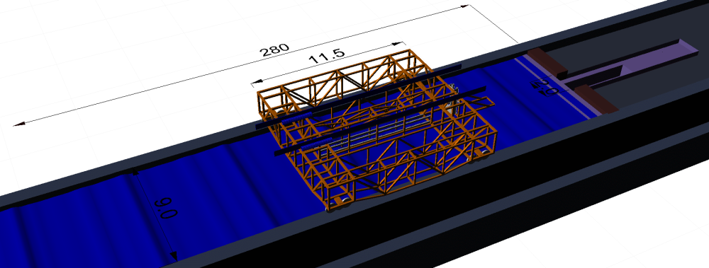
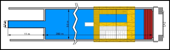
| Length | [m] | 280 |
| Width | [m] | 9 |
| Depth | [m] | 4.5 |
| Towing Carriage | ||
| Max. Towing Velocity | [m/s] | 7.5 |
| Precision Carriage Velocity | [mm/s] | 0.6 |
| Wave Generator | ||
| Max. Wave Height | [m] | 0.3 |
| Types of Waves | regular, irregular, wave trains | |
Main Parameter |
H29 | H39 | |
| Propeller thrust | T<max [N] | 400 | 1000 |
| Propeller torque | Qmax [Nm] | 15 | 55 |
| Propeller R.P.M. | nmax [s-1] | 60 | 60 |
| Max. Propeller Shaft Inclination | [°] | 30 | 30 |
Main Parameter |
R25 | R31 | R73 | R40 | |
| Propeller Thrust | Tmax [N] | 100 | 250 | 600 | 150 |
| Propeller torque | Qmax [Nm] | 4 | 10 | 30 | 6 |
The dynamometers are capable for experiments with shaft inclination.
Open Water Carriages FK1, FK4
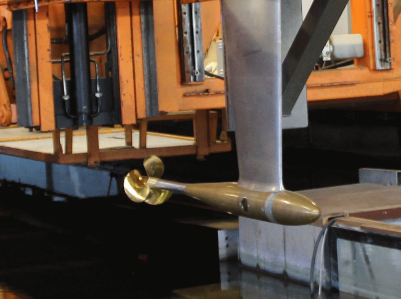
The open water carriages FK1 and FK4 offer the possibility to perform tests with internal propulsion dynamometers for ship models. Custom dynamometers from Kempf and Remmers are used for the measurement range and for the FK4 carriage, the counter rotating dynamometer R40 from Kempf & Remmers is used. A measurement balance for nozzles can also be mounted on both devices.


Technical Specifications |
|
| Nd:YAG double pulse laser | 190 mJ, max. Frequency 15 Hz |
| Resolution CCD cameras | 2 Megapixel (1600×1200) |
| Colour depth/grey levels | 12 bit |
| Max. recording frequency | 14.5 Hz |
| Field of view | 100×100 up to 800×1000 mm |
| Number of stereoskopic recordings per measurement run at 14.5 Hz | 1200 |
| Max. submersion depth of PIV probe | 0.7 m |
| Max. submersion depth of single system components | 4.5 m |
For the measurement of forces and moments on bodies within flows, 3 component and 6-component balances are available with different measurement ranges and areas of operation. The balances R37SR1 … 6 are suitable for open water tests and for use in models. The devices are designed for measurement of rudder and fin forces and to capture integral forces on thrusters. The majority of balances are equipped with a rotary table, which can be set with the angle statically and dynamically. For use with thrusters the balances are equipped with a drive motor. The total torque is detected by a torque sensor.
The balance R200 is designed for open water tests with large motors and for general force measurements. It is additionally equipped with a turntable, drive motor and torque sensor.
The balances R100, R 250 and R 350 can be used for force measurements on ships and floating or submerged structures. These allow the change in yaw, trim and angle of heel, and the application of different connections.

Technical Specifications Multicomponent Balances |
||||||||
| Main Parameters | R37SR 1, 2 | R37SR 3, 4 | R37SR 5, 6 | R200 | R100 | R250 | R300 | |
| Components | 3 | 6 | 3 | 6 | 3 | 6 | 3 | |
| Forces | Fmax [N] | 500 | 500 | 1000 | 2000 | 1000 | 2500 | 3500 |
| Torque | Qmax [Nm] | 20 | 20 | 20 | 20 | — | — | — |
For measuring the forces on VSP (Voith Schneider Propeller) drives, special measuring balances have been developed which, in comparison with the conventional VSP balances, enable the measurement of thrust, two lateral forces, and the drive torque. The VSP balances can be used in ship models, in the towing tank, and in the cavitation tunnel.
Technical Specifications |
|
| Measurement of | |
| Thrust | ✓ |
| Lateral Forces | 2 |
| Drive torque | ✓ |
| Torque | ✓ |
| Max. force component [N] | 200 |
| Max. torque [Nm] | 8 |
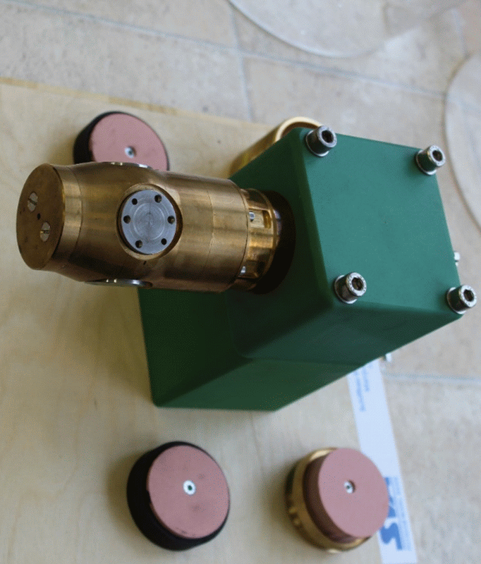
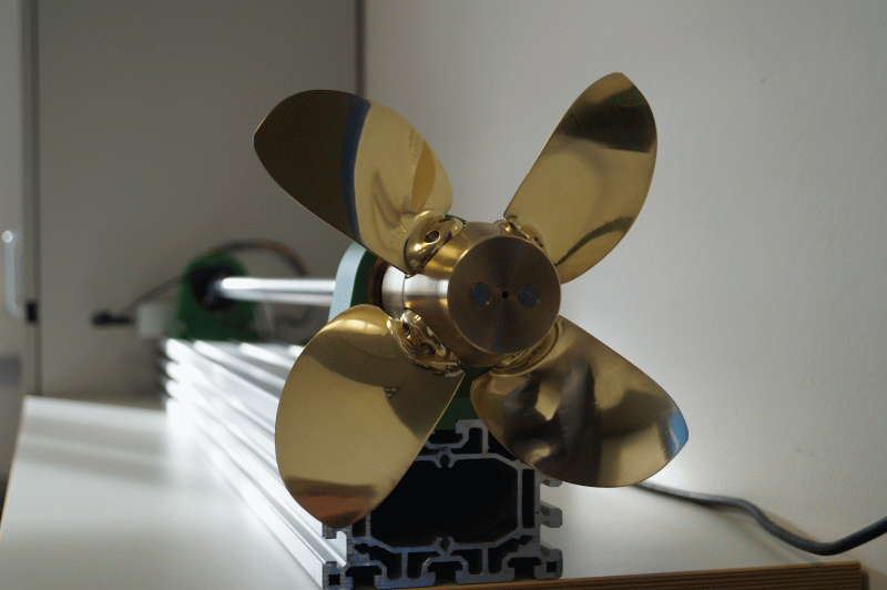
With an adjustable blade hub, the dynamic adjustment of ptich during testing is possible, for example, for stopping manoeuvres. The adjustable blade hub achieves the change of blade pitch with a multiphase motor with two limit switches built in which switch off the engine at ± 30° adjustment. The average pitch is marked on the inner hub. The angle is measured with a potentiometer. The hub is mounted on a carbon ring. The control data and the values of the potentiometers are transmitted via a slip ring assembly.
Main Parameters |
||
| Hub Diameter | mm | 60 |
| Hub Length | mm | 57 |
| Number of Blades | — | 4 |
| Propeller Diameter | mm | 250 |
Context Related References / Research Projects
[1] Steinwand, M.: Optimierung des Stoppmanövers mit Verstellpropellern und Hybridantrieben, 9. SVA-Forschungsforum, Potsdam, 28. Januar 2016
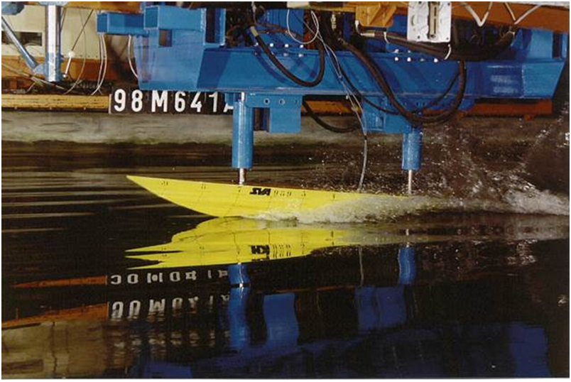
To investigate this problem experimentally, a hydraulic slamming system was developed in the SVA. With this system, pitching, heaving and coupled movements can be introduced with a frequency of up to 2.0 Hz and an amplitude of up to 10 cm on model ships. It can test models with a length of 5.5 m and a moving mass of 500 kg. By measuring pressure variations in the kHz range on up to 30 measurement points, local peak pressures can be identified.
Technical Specifications |
|
| Max. Frequency | 2 Hz |
| Max. Amplitude | 0.1 m |
| Max. Model Length | 5.5 m |
| Max. Mass | 500 kg |
| Max. # Measurement Points | 30 |
Context Related References / Research Projects
[1] Fröhlich, M.: Einsatz eines Schwingungsoszillators auf hydraulischer Basis zur Untersuchung der Slammingbelastung von Schiffen, STG-Sprechtag „Schiffe im Seegang“, Hamburg, Oktober 1998
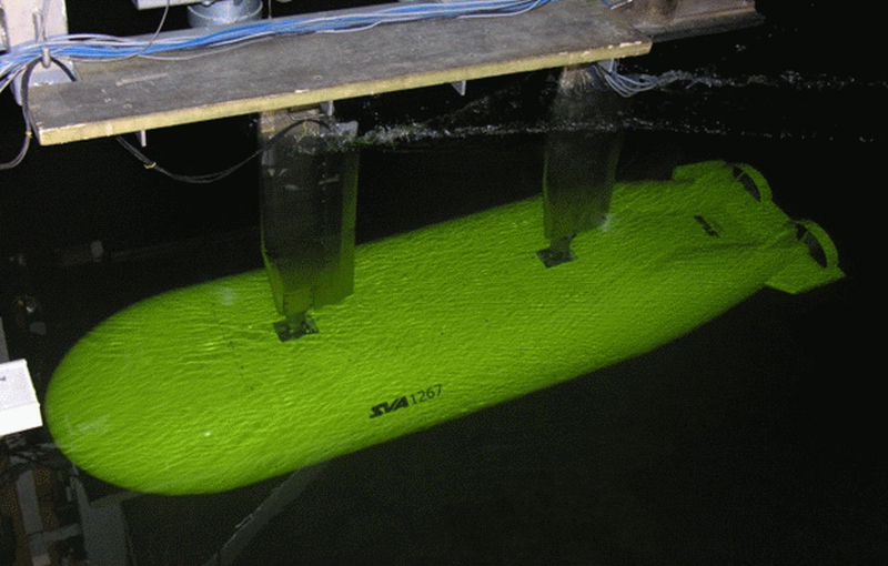
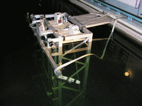
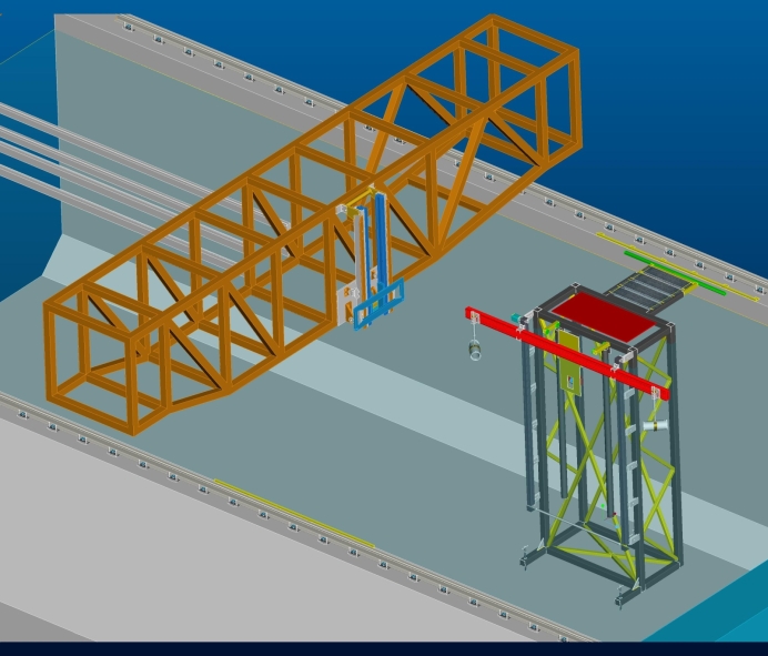
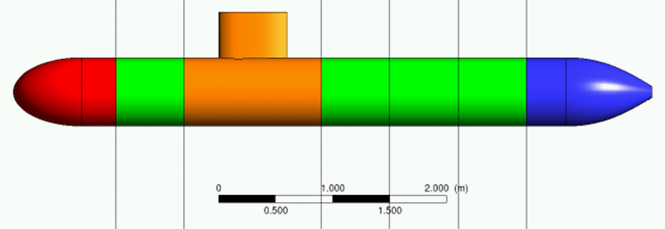
Measurements with submerged bodies are performed on originals or copies in original size and scale models. The range of test objects extends from submersibles such as ROVs and AUVs to submarines and special investigations of marine life and divers.
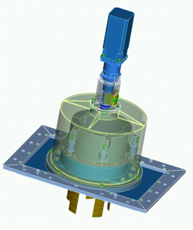
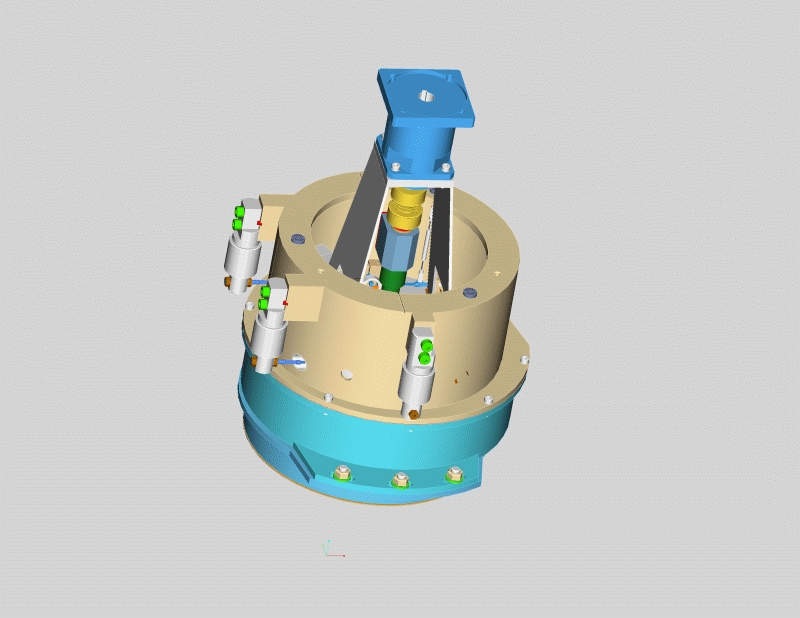
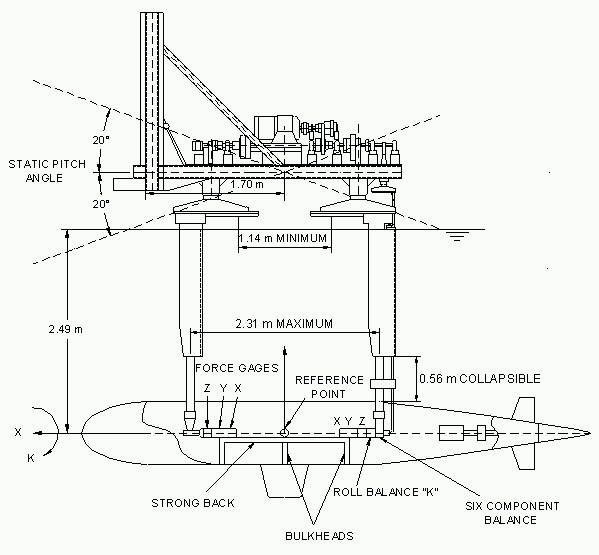
To determine the motion behaviour of underwater vehicles in the vertical and horizontal plane, and also for resistance and propulsion tests as well as wake measurements, the SUBPMM (Submarine-Planar-Motion- Mechanism) system is used. What is special about this system is that the measuring points of the forces are placed within the model and hence the influences of the towing device can be eliminated. The system is adaptable for model sizes from 1 to 6m and depths of 0.5 to 2.5m. For driving the models, enclosed motor dynamometer modules are used with different sizes to choose from.
For the determination of the motion behaviour of underwater vehicles, the simple drag motion of the model can be superimposed with an additional level of movement with the SUBPMM system. In addition, the angle of attack of the model as well as the control arms can be varied. Thus, it is possible to determine the coefficients for the equations of motion.
The SUBPMM system is also used for resistance and propulsion tests. For wake measurements a probe with pressure sensors is used which can be adjusted automatically.
In the R&D projects, “Scale Effects in Determining the Manoeuvring Behaviour of Underwater Vessels by Model Testing” [3], “Correlation of Resistance of Submerged Bodies” [1], “Interference Phenomena in Substructures of Submerged Bodies” [2] and “Influence of the Reynolds Number carried out in the Thrust Deduction Fraction”[4] Geosim-tests and calculations for underwater vessels for motion behaviour, resistance and interference phenomena were executed. The results of these studies are incorporated into the correlation for full scale predictions.

Context Related References / Research Projects
[1] Grabert, R., Rieck, K.: Skalierung von Widerstandsversuchen mit U-Booten, VSM(2007)
[2] Nietzschmann, T.: Interferenzerscheinungen bei Substrukturen von getauchten Körpern”, FuE-Sachbericht (2012)
[3] Steinwand, M.: Maßstabseffekte bei der Bestimmung des Manövrierverhaltens von Unterwasserfahrzeugen durch Modellversuche, 2. SVA-Forschungsforum, Potsdam, 29. Januar 2009
[4] Hellwig-Rieck, K.: Einfluss der Reynoldszahl auf die Sogziffer, 4. SVA-Forschungsforum, Potsdam, 27. Januar 2011