- Through the work of the propeller in the irregular wake field, periodically fluctuating forces and moments occur which are introduced via the shaft bearings in the hull.
- The propeller, with its rotating pressure field, generates pulsating compressive forces on the hull. Through the work of the propeller in the irregular wake field additional periodic pressure pulses arise, which can be significantly increased by temporarily occurring cavitation at the propeller blade.
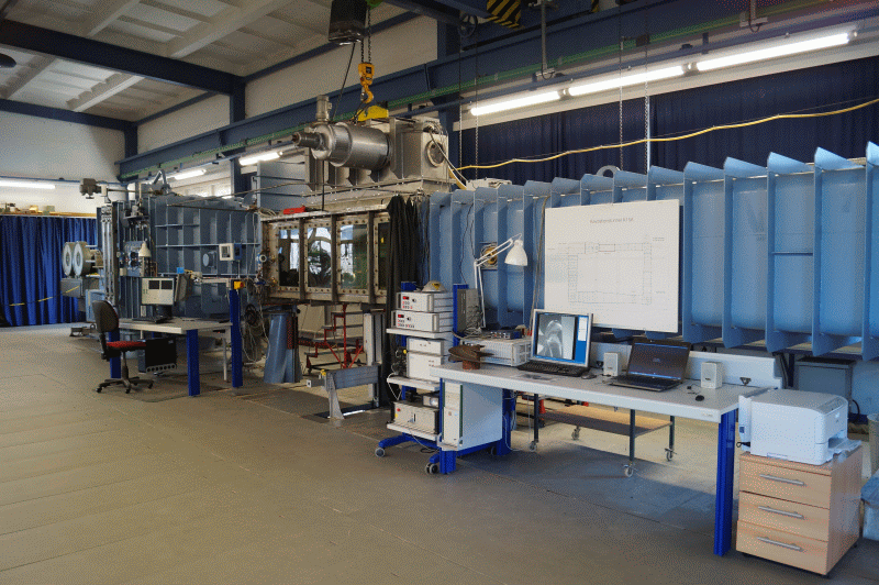
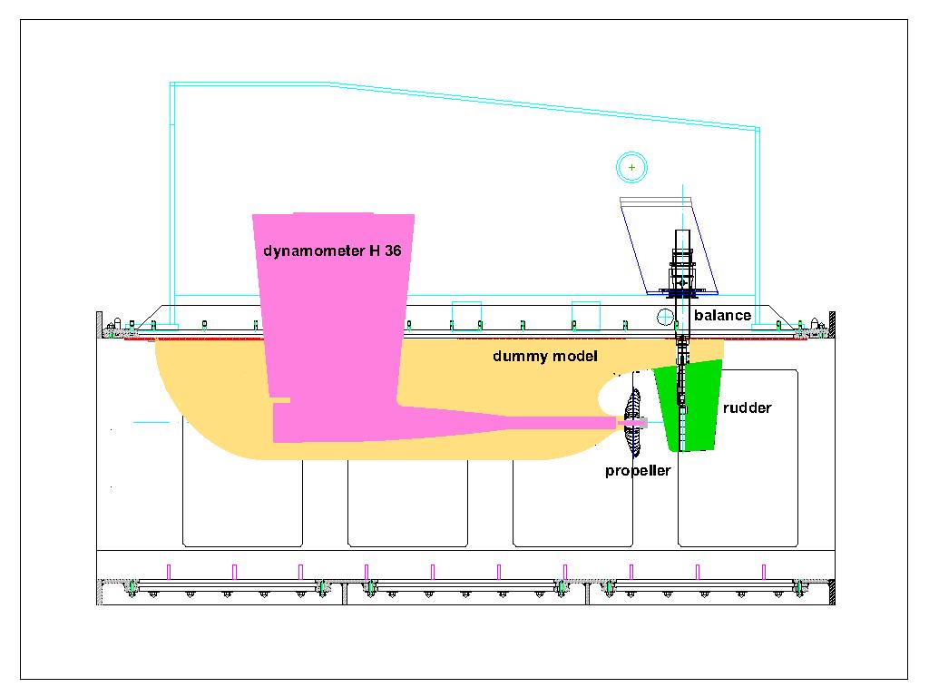
The measurement of the pressure pulses induced by the propeller on the hull of the vessel is accomplished in the large test section (2600 mm x 850 mm x 850 mm) of the cavitation tunnel K15A from Kempf & Remmers [1], [2], [3]. A typical experimental setup for propeller ships is shown. The propeller is driven by the dynamometer H36. Up to 16 pressure sensors are positioned above the propeller in the stern of a dummy model. The length of the dummy models (shortened models with stern contours to scale), is between 2.2 and 2.7 meters. With the dummy model, the predicted three-dimensional inflow to the propeller at the Reynolds number of the vessel is simulated. Within the framework of R & D projects or, for comparison with measurements on ship models, the wake field distribution of the model can be simulated.
Cavitation trials and pressure pulse measurements are based on systematic series of experiments and full-scale measurements to determine and compare the influence of various parameters. The experiments are carried out at high rotational speeds of the propeller model (n > 25 s-1). The oxygen content of the water as a measure of the gas content of the water is controlled at a saturation degree of α / αS > 60%, in order to minimize the influence of the nuclei content of the water and thus the scale effects on the cavitation. In addition, the pressure pulse measurements are performed according to predefined test procedures which, among other things, include a run-in phase of the testing equipment of at least an hour and a range of additional measurements with variations of propeller load and cavitation numbers and variations of the experimental parameters.
The prognosis and simulation of the inflow at the propeller according to the conditions on the ship is a central point of the R & D work on the development of experimental methods for cavitation trials and pressure fluctuation measurements [4], [5]. Therefore, in preparation for the measurements, CFD calculations are performed for the flow around the ship as well as for the flow around the model. Before carrying out the cavitation and pressure pulse measurements, the velocity distribution in the propeller plane of the dummy model will be measured with the LDV system.
Context Related References / Research Projects
[1] Selke, W.; Heinke, H.-J.: Propelleruntersuchungen im Kavitationstunnel der Schiffbau-Versuchsanstalt Potsdam, STG-Jahrbuch 1990
[2] Schmidt, D.; Selke, W.; Gerchev, G.: Comparative Joint Investigations in the Cavitation Tunnels of SVA and BSHC on the Prediction of Propeller Induced Pressure Pulses, Schiffbauforschung 31/1, 1992
[3] Heinke, H.-J.: The Influence of Test Parameters and Wake Field Simulation on the Cavitation and the Propeller Induced Pressure Fluctuations, Jahrbuch der Schiffbautechnischen Gesellschaft, 97. Band, 2003
[4] Heinke, H.-J.; Hellwig-Rieck, K.: Investigation of Scale Effects on Ships with a Wake Equalizing Duct or with Vortex Generator Fins, Second International Symposium on Marine Propulsors, smp’11, Hamburg, Germany, June 2011
[5] Kleinwächter, A.; Hellwig-Rieck, K.; Ebert, E.; Kostbade, R.; Heinke, H.-J.; Damaschke, N. A.: PIV as a Novel Full-Scale Measurement Technique in Cavitation Research, Fourth International Symposium on Marine Propulsors, smp’15, Austin, Texas, USA, June 2015