Author: pa

Cavitation Test


Cavitation tests are carried out in the cavitation tunnel K15A from Kempf & Remmers. The cavitation tunnel has two test sections with cross sections 600 mm x 600 mm and 850 mm x 850 mm and a length of 2.60 m. In the small test section, cavitation tests are predominantly performed with propellers for fast ships and special tests such as measurements on profiles and wings, speed measurements with LDV or PIV, erosion tests, and calibrations of speed measurement systems.

The investigation of the behaviour of propeller cavitation in the wake field of a vessel and measurement of propeller-induced pressure pulses [2] – [6] are carried out in the large test section of the cavitation tunnel. The typical experimental setup for a single-screw vessel is shown in the schematic diagram. The propeller is driven by the dynamometer H36 by Kempf & Remmers. The simulation of the wake, calculated for a Reynolds Number of the full-scale ship, is done with a dummy model and additional grids. The dummy models are up to 2.60 m long and geometrically similar to the ship in the stern area. The blocking of the measuring cross section is within the range between 10 to 22 %. High-Speed recordings of cavitating propulsion systems can be found here.


Context Related References / Research Projects

[1] Potsdam Propeller Test Case: https://www.sva-potsdam.de/en/potsdam-propeller-test-case-pptc
[2] Schmidt, D.: Propellererregte Druckschwankungen an Frachtschiffen mit großen langsamlaufenden Propellern, Schiffbauforschung 26 (1987) 3
[3] Selke, W., Heinke, H.-J.: Propelleruntersuchungen im Kavitationstunnel der Schiffbau-Versuchsanstalt Potsdam, Jahrbuch der STG, 84. Band, 1990
[4] Schmidt, D., Selke, W., Gerchev, G.: Comparative Joint Investigations in the Cavitation Tunnels of SVA and BSHC on the Prediction of Propeller-Induced Pressure Pulses, Schiffbauforschung 31(1992)1
[5] Heinke, H.-J.: Einfluss des Nachstroms auf die Kavitation und Druckschwankungen eines Propellers, 13. SVA-Forum, Potsdam, 29. August 2006
[6] Heinke, H.-J.: The Influence of Test Parameters and Wake Field Simulation on the Cavitation and the Propeller Induced Pressure Fluctuations
Jahrbuch der Schiffbautechnischen Gesellschaft, 97. Band, 2003

Open Water Test

Freifahrt_DiagrammFreifahrt_Test_arrangement_for_open_water_test_small

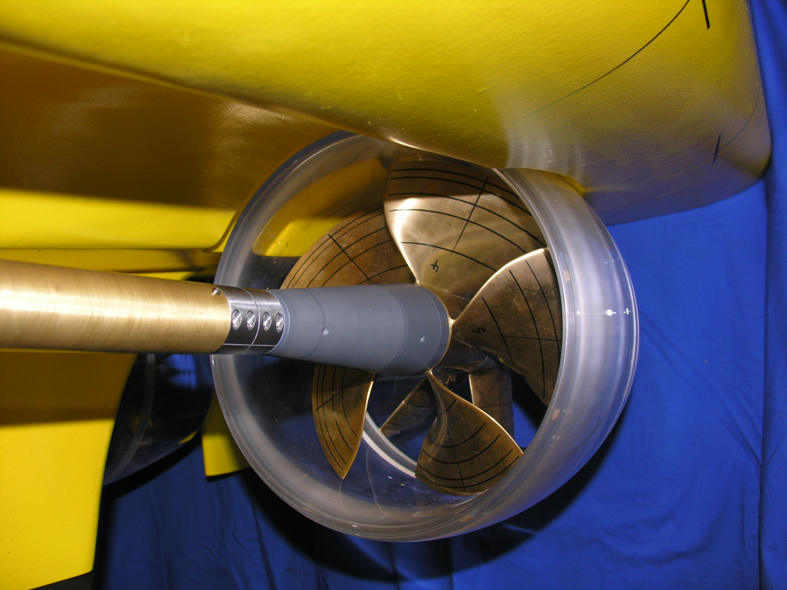
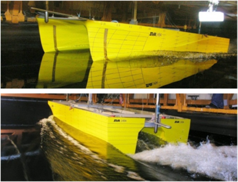
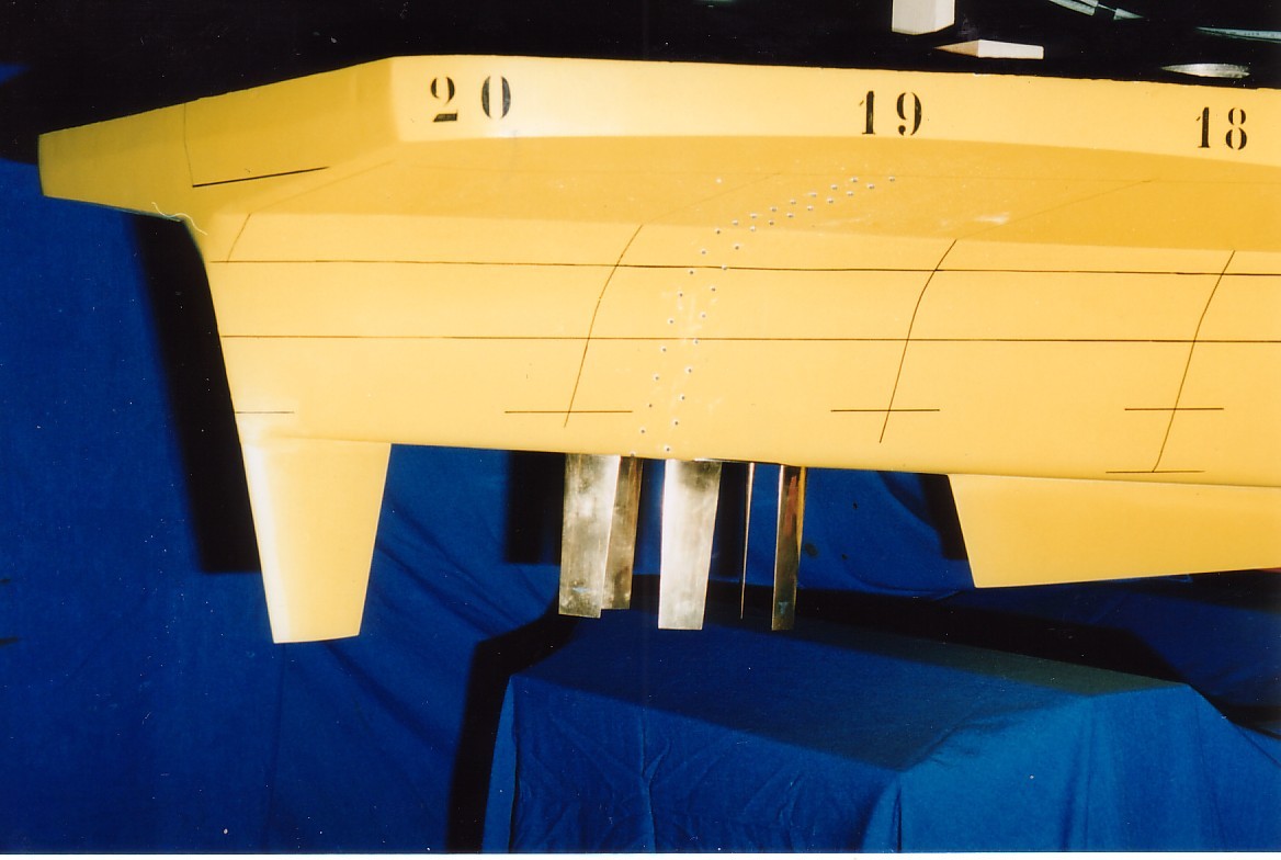
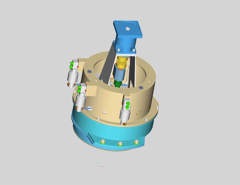
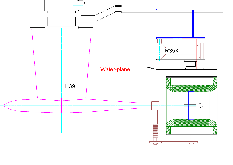
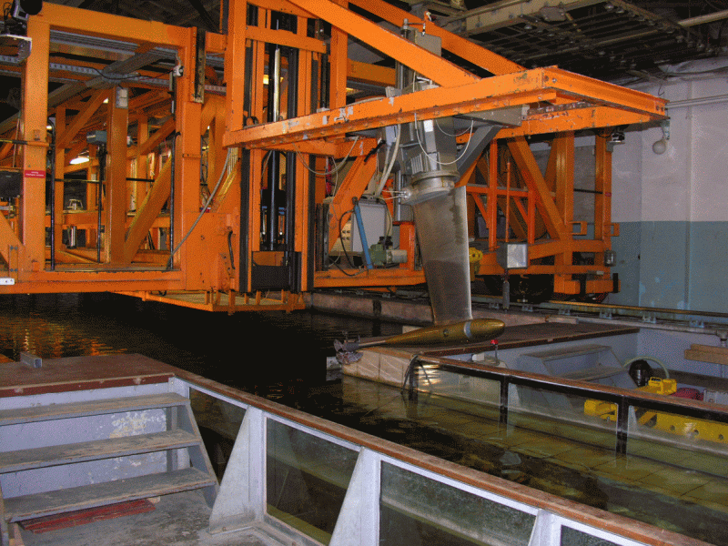
In open water tests the characteristics of the propeller are measured in homogeneous inflow. Open water tests are mostly performed in the towing tank. For this purpose, the SVA utilises open water carriages and propeller dynamometers. In open water carriage FK1 Kempf & Remmers, the integrated inner dynamometer can be used with different measuring ranges to measure with the highest possible accuracy. In addition, the open water carriage can be used to measure forces and moments on the individual blades of the propeller. For this purpose, measuring hubs have been developed for propellers with three, four and five blades. For the investigation of counter rotating propellers, the dynamometer R40 Kempf & Remmers is used. The dynamometer is installed in the open water carriage FK4 and can be driven by one or two motors to examine the counter rotating propellers with fixed or variable speed ratios. Most open water tests are carried out with the dynamometers H29 and H39 from Kempf & Remmers. The dynamometers differ in size and range and are appropriately selected to match the model propeller.

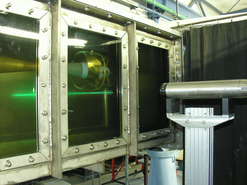
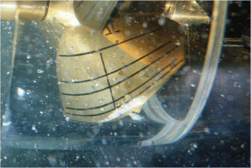
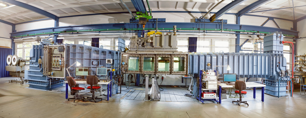
The characteristics of the propeller can also be determined in the cavitation tunnel K15A. The influence of the limited size of the cross section on the flow velocity or the thrust and torque of the propeller is considered in the test evaluation. The SVA uses the method of Glauert [1] to calculate the wall correction. The cavitation tunnel K15A is equipped with the dynamometers J25 and H36 from Kempf & Remmers. The dynamometer H36 can be used to measure the forces and moments on the individual blades of the propeller by means of a measuring hub.

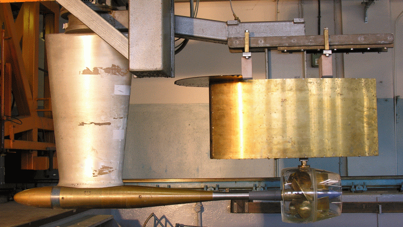
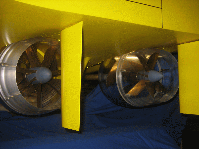
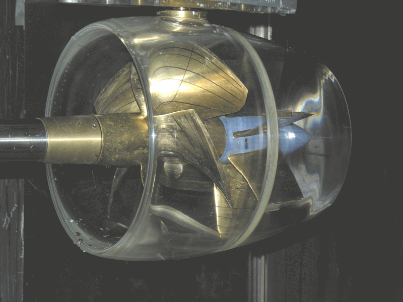
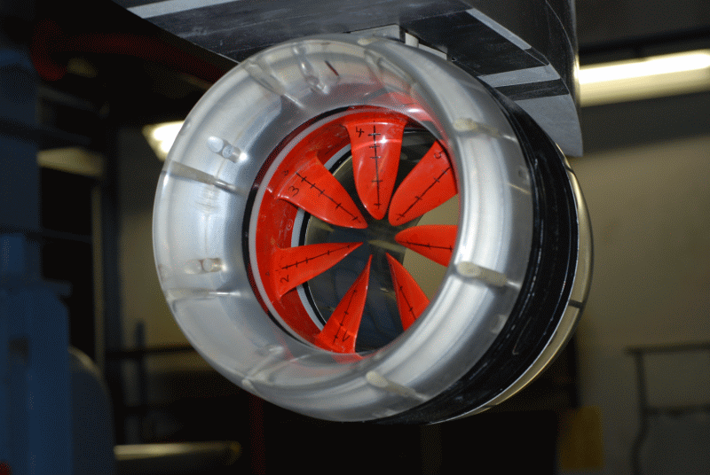
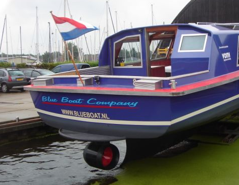
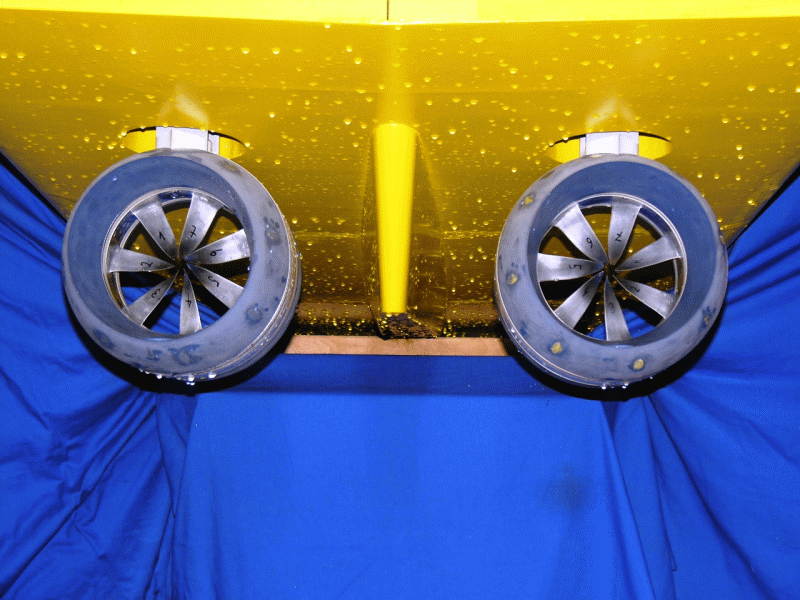
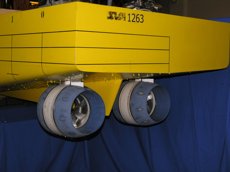
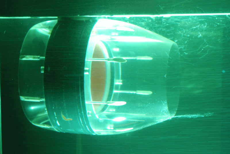
All dynamometers can be combined with single and three-component balances. Thus, the measurement of the open water characteristics of jet propellers or complex propulsion systems is possible. In addition, two dynamometers and balances can be used together to test counter rotating propellers, tandem propellers or other special propulsion systems.

The shaft inclination of dynamometer H29, H39 and H36 can be varied. The dynamometer H39 and H36 can also be equipped with devices for the measurement of transverse and vertical forces of the propeller.

The detailed description of the experimental procedures and evaluation is contained in the documentation of the Potsdam Propeller Test Case (PPTC) [2].

Freifahrt_K15A_SVA-Potsdam_2015_small


Context Related References / Research Projects

[1] Glauert, H.: Wind Tunnel Interference. W. F. Durand, Aerodynamic Theory, Vol. IV, Berlin 1935, Division L: Airplane Propellers; 296 – 306
[2] smp’11: 2nd Symposium on Marine Propulsors & 1st Workshop on Cavitation and Propeller Performance, June 17 -18, 2011, Hamburg, Germany

Waterjet

Waterjet_einzeln
Waterjet_Propversuche
The main components of the deep submerged water jets (DWJs) are rotor, stator and nozzle. The combination of the rotor and stator ensures a nearly swirl-free jet beam (minimum rotational loss). Through the nozzle geometry, the velocity and the pressure can be influenced within the linear jets (deceleration nozzle) in order to reduce the occurrence of cavitation.

The linear jet is located underneath the ship’s hull. Basic research in the R & D project “Development of Linear Jets for Yachts” [1] showed that the deep submerged water jet is a propulsion system with high efficiency and good cavitation characteristics and can be used, in particular, for fast ships and ships with draught restrictions. During the period from 2000-2005, studies and projects were conducted at the SVA for ships with deep submerged waterjets in collaboration with the industry and manufacturers of waterjets. At the end of 2005, Voith Turbo Schneider Propulsion GmbH & Co. KG [4] (VOITH) took over the development and production of the DWJs renaming them Voith Linear Jets (VLJ). Together with Voith, the R & D project “Development and Optimisation of Deeply Submerged Waterjets” (2006 – 2007) and “Propulsion of Ships with Deeply Submerged Waterjets” (2008 – 2010) were carried out in the SVA [2], [4]. The main goals were the optimisation of the submerged water jets, the determination of the open water characteristics and cavitation characteristics of DWJs, the hydrodynamic integration of DWJs in ship design, the development of the experimental methodology and predicting methods as well as identification of the propulsion characteristics of ships with DWJs. In 2012 VOITH received the first order for a twin set of Voith Linear jets (VLJ) from the British company Turbine Transfer Ltd. for a Wind Farm Support Vessel (WSV). In 2013 the VLJs were developed and manufactured by VOITH. At SVA, systematic experiments [3] and CFD calculations were performed referencing the full-scale measurements from the WSV to check the prediction methods.


Waterjet_im_KT_frontal_smallWaterjet_am_DynamometerWaterjet_Heck_smallWaterjet_im_KT_smallWaterjet_DetailModell_VWJ_small


Context Related References / Research Projects

[1] Bohm, M., Jürgens, D.: LINEAR-Jet: A propulsion system for fast ships, PRADS 1998, The Hague, The Netherlands
[2] Heinke, H.-J., Hellwig; K.: Tiefgetauchter Waterjet – Entwicklungsstand und Ausblick, Marineforum 12/2005
[3] Heinke, H.-J.: Latest Hydrodynamic Results of the Voith Linear Jet, 5th Symposium on Voith Schneider Technology 2014, Heidenheim
[4] Jürgens, D., Heinke, H.-J.: Untersuchung tiefgetauchter Waterjets, STG-Hauptversammlung, Hamburg, Jahrbuch der Schiffbautechnischen Gesellschaft, 100. Band, 2006


Linearjet

Lorem ipsum dolor sit amet, consectetur adipiscing elit. Curabitur lectus elit, porttitor quis placerat eget, porttitor eget nunc. Aliquam vel ex lectus. Sed ultricies sed nisi vitae faucibus. Integer sit amet dapibus dolor. Proin tincidunt orci a neque convallis tincidunt. Sed consectetur vel ex sit amet euismod. Praesent commodo ex id ligula porttitor semper. Morbi tempus justo id nisl mattis, eu laoreet sapien suscipit. Aenean est lacus, sodales nec varius vel, convallis sit amet nisl. Cras eleifend, ante vel tempus aliquam, tellus orci tristique nisl, nec convallis diam metus at diam. Proin egestas mauris ligula, in elementum ex efficitur eget. Praesent viverra commodo lacus, eget molestie dui molestie sed. Aliquam nec mollis quam. Phasellus euismod consectetur tincidunt. Phasellus sit amet felis elementum, bibendum dolor quis, blandit magna.

Curabitur eu massa vitae turpis laoreet molestie in eu velit. Nunc in condimentum nisl. Suspendisse potenti. Nullam ante ex, varius nec dignissim faucibus, suscipit vel eros. Aliquam condimentum nisi sit amet est vestibulum tincidunt. Quisque nisl enim, tempor in porttitor sed, ornare ac massa. Mauris sed convallis nisl. Aenean volutpat finibus turpis. Ut porta sagittis ligula congue vestibulum.

Vertical Axis Rotors

VSP_am_Modell_SeiteVSP_Antrieb_CAD_small

Vertical axis rotors like the Voith Schneider Propeller (VSP) are special propulsion systems that give ships very good maneouvrability with very short control times. These systems are therefore often installed on double-ended ferries and special purpose vessels. In the SVA many ships with VSP’s were examined, such as tugboats, double-ended ferries with 2 and 4 VSP’s, and offshore supply ships. To get a deeper insight into the mechanism of action of Voith Schneider Propellers, several research projects were conducted [1], [2] in the SVA Potsdam. Among other things, the interaction of VSP and hull on double-enders [3], [4] was investigated. Here, a special SVA measuring balance was developed which in comparison to the standard methods, enables the measurement of the thrust in the model test and thus to determine the interaction parameters in propulsions tests. The interaction parameters can provide information on optimisation potentials.

In the project “Offshore Support Vessels with Voith Schneider Propellers” basic investigations were performed for the propulsion of OSV’s with VSP’s [6]. The focus was again on the interaction between VSP and hull. Simultaneously, the current methods of evaluation have been reviewed.

For model testing, VSP models are provided by the Voith company. For normal power and speed prediction, the thrust measurement on VSP’s is not absolutely necessary. However, the additional amount of preparation and testing time lends itself to optimisation questions.


Context Related References / Research Projects

[1] Heinke, H.-J.: Model tests with Voith Schneider Propellers at high thrust coefficients, Hydrodynamic Symposium – Voith Schneider Propulsion, Heidenheim, März 2006
[2] Heinke, H.-J.: High-Speed Camera Observations of the Cavitation at a Voith Schneider Propeller, 2nd Symposium Voith Schneider Technology, Heidenheim, June 2008
[2] Jürgens, D.; Grabert, R.: New Hydrodynamic Aspects of Double Ended Ferries with Voith-Schneider Propeller, 2nd International Conference on Double Ended Ferries, Alesund, Norway, 2003
[4] Grabert, R.: New Insight into the Hydrodynamics of Double-Ended Ferries with Voith Schneider Propellers, 3rd Hydrodynamic Symposium on Voith Schneider Propulsion, Constance, 16 – 18 June 2010
[5] Grabert, R.: Analysis of the Interaction VSP – Hull of Modern OSV, 4th Hydrodynamic Symposium on Voith Schneider Propulsion, Heidenheim, 12 – 14 June 2012
[6] Heinke, C.: Investigations of OSV with VSP Propulsors at SVA Potsdam, 5th Hydrodynamic Symposium on Voith Schneider Propulsion , Heidenheim, 30.9. – 2.10. 2014

Inline Thruster

ILT_rot_small

An inline thruster is an electric ring motor with a rotor and nozzle combined in a powerful propulsion system without shaft and gearbox. Four inline thrusters with a rotor diameter of 170 mm have been developed in the SVA for model tests. The models are studied in open water and cavitation tests. In addition, velocity measurements, dynamic flow monitoring and open water experiments at different azimuth angles and in off-design conditions were carried out for various industrial applications.

The forces and moments on the different elements of the inline thrusters were calculated in the model and at full-scale. The results of these calculations were the basis for the investigation of the Reynolds number effects and for the optimisation of the rotor and nozzle geometry.
Propulsion and maneuvering tests showed the applicability of inline thrusters for main propulsion system of ships [1], [2].


ILT_am_Grachtenboot_DetailILT_an_M1263_1_heck_smallILT_an_M1263_2_bb_stb_smallILT_im_KT_small

ILT_CFD_unorm_130_m_RahmenILT_Einbau_small


Context Related References / Research Projects

[1] Heinke, C.: Flachwassergeeignete Propulsionssysteme mit hoher Effizienz, SVA-Bericht 3502, FuE-Abschlussbericht, Potsdam, November 2008
[2] Heinke, H.-J.: Inline Thruster als Hauptantriebssystem, SVA-Bericht 3670, FuE-Abschlussbericht, Potsdam, Mai 2010