Please read more about our 3 components LDV system here.
Author: pa
ESD – Energy Saving Devices
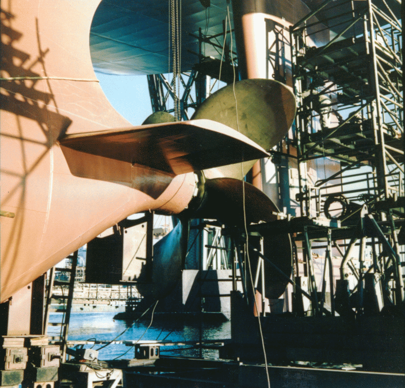
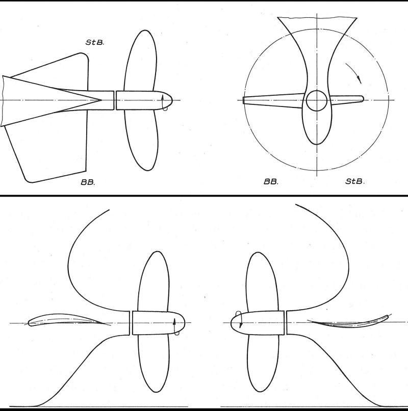
The term “Energy Saving Device” (ESD) encompasses the measures and methods for saving energy in ship operation compared to “conventional” ships. ESDs include, among other things, the asymmetric after-body (“stern bulb” form), propeller, nozzles, guide fins, and the rudder, alone and in combination.
The development of ESDs has been worked on already since the 70s. The focus was on the influence of after-body forms and bulges, propulsion and vibration excitation, design and testing of contra-rotating and overlapping propellers, and developing inflow-improving nozzles [1], [2], [3].
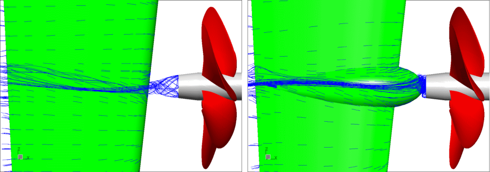
Asymmetric after-bodies and guide fins were used in the context of propulsion optimisation of ships for generating a pre-swirl in the propeller inflow to reduce the rotational losses of the propeller. The research and development in this area led to the SVA guide fin systems. Model tests with different types of ships and full-scale measurements show a potential of 2 to 5 % power savings through the use of SVA guide fin systems [4], [5], [6]. Various R & D projects have been processed in order to improve the design of propellers and ESDs. Potential flow methods are used for the design and optimisation of propellers. Viscous calculation methods and experiments are used to verify the design, the prognosis of scale effects and applied to the design and optimisation of propulsion systems such as ducted propellers, thrusters and ESDs. To check the design of the propeller, speed measurements are performed on propeller boss cap fins and rudder. The SVA-developed HVV outlet cover (Hub Vortex Vane), leads to a reduction of the hub vortex and reduces the energy loss of the propeller in the hub area.Systematic CFD calculations are performed for analysis of the effectiveness of Costa Bulb on rudder and to derive design cues [7]. These works were continued in R & D project BossCEff – “Increasing the Effective Degree of Propulsion and Controlling Boss Vortex Cavitation Through Improved Consideration of the Interaction Between Propeller Wash and Boss Cover” [8], [9]. In cooperation with the project partners Technical University of Hamburg-Harburg, The Institute of Fluid Dynamics and Ship Theory (FDS), and the Mecklenburger Metallguss GmbH (MMG), special propeller flow caps were developed and studied for use in rudders with Costa Bulbs and propeller boss covers with fins.
The development of ESDs has been worked on already since the 70s. The focus was on the influence of after-body forms and bulges, propulsion and vibration excitation, design and testing of contra-rotating and overlapping propellers, and developing inflow-improving nozzles [1], [2], [3].
Asymmetric after-bodies and guide fins were used in the context of propulsion optimisation of ships for generating a pre-swirl in the propeller inflow to reduce the rotational losses of the propeller. The research and development in this area led to the SVA guide fin systems. Model tests with different types of ships and full-scale measurements show a potential of 2 to 5 % power savings through the use of SVA guide fin systems [4], [5], [6]. Various R & D projects have been processed in order to improve the design of propellers and ESDs. Potential flow methods are used for the design and optimisation of propellers. Viscous calculation methods and experiments are used to verify the design, the prognosis of scale effects and applied to the design and optimisation of propulsion systems such as ducted propellers, thrusters and ESDs. To check the design of the propeller, speed measurements are performed on propeller boss cap fins and rudder. The SVA-developed HVV outlet cover (Hub Vortex Vane), leads to a reduction of the hub vortex and reduces the energy loss of the propeller in the hub area.Systematic CFD calculations are performed for analysis of the effectiveness of Costa Bulb on rudder and to derive design cues [7]. These works were continued in R & D project BossCEff – “Increasing the Effective Degree of Propulsion and Controlling Boss Vortex Cavitation Through Improved Consideration of the Interaction Between Propeller Wash and Boss Cover” [8], [9]. In cooperation with the project partners Technical University of Hamburg-Harburg, The Institute of Fluid Dynamics and Ship Theory (FDS), and the Mecklenburger Metallguss GmbH (MMG), special propeller flow caps were developed and studied for use in rudders with Costa Bulbs and propeller boss covers with fins.
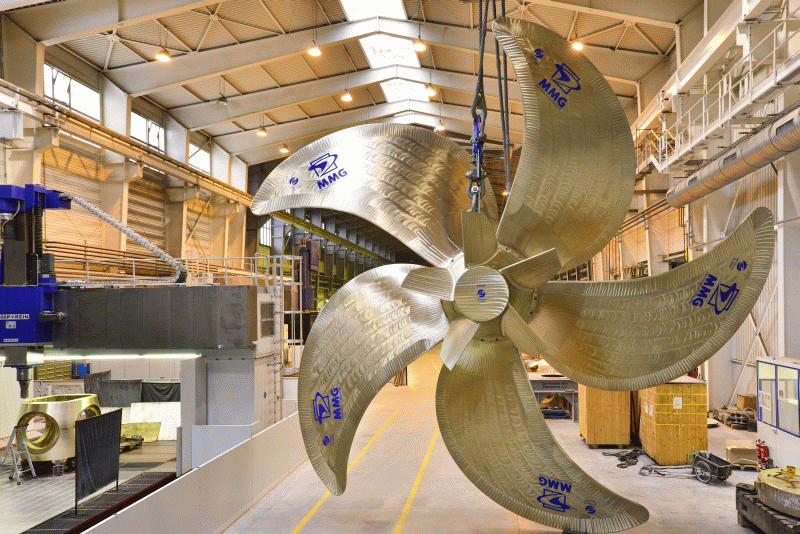
The Mecklenburg Metallguss GmbH developed in the collaborative projects BossCEff a new energy-saving propeller cap, MMG ESCAP®.
The propeller caps improve propulsion characteristics of the vessel on existing propellers and on propeller redesign projects. The ESCAP®, among others, has also been successfully applied in newly designed propellers.
The following maximum power savings were achieved for ships with ESDs by investigations of SVA [11], [12]:
| – Twisted Rudder | up to 1,4 % |
| Costa-Bulb with Twisted Rudders | up to 3,7 % |
| Costa-Bulb with Conventional Rudders | up to 3,5 % |
| Boss Cap Fins | up to 3,2 % |
| Propeller Redesign | up to 14 % |
| Wake Equalising Duct | up to 4,8 % |
| Becker Mewis Duct® | up to 10 % |
| Bulbous Bow Retro-fit | up to 21 % |

Context Related References / Research Projects
[1] Schmidt, D.: Propulsionsuntersuchungen mit Einzelpropeller und Gegenlaufpropeller am Modell eines Containerschiffes, Schiffbauforschung 14 1/2/1975
[2] Schmidt, D.: Der Einfluss der Form des Heckwulstes auf die Schwingungserregung durch den Propeller für ein Containerschiff, Schiffbauforschung 21 1/1982
[3] Schmidt, D.: Die Reduzierung der propellererregten Schwingungen durch nachstrombeeinflussende Änderungen am Hinterschiff,
Schiffbauforschung 23 3/1984
[4] Mewis, F., Peters, H.-E.: Verbesserung der Propulsion durch ein neuartiges Flossensystem Intern. Rostocker Schiffstechnisches Symposium, Schiffbauforschung, Sonderheft, Bd. 1, 1987
[5] Peters, H.-E., Mewis, F.: Das Leitflossensystem der SVA am Containerschiff Typ Saturn, HANSA Nr. 17/18, 1990
[6] Schmidt, D.: Nachrüstung von Motorgüterschiffen ermöglicht Leistungseinsparung, Binnenschiffahrt – ZfB Nr. 9, Sept. 1995
[7] Lübke, L.: Numerical Simulation of the Viscous Flow around Costa Bulbs, NUTTS 2002, Nantes, August 2002
[8] Greitsch, L., Pfannenschmidt, R., Abdel-Maksoud, M., Druckenbrod, M., Heinke, H.-J.: BossCEff – Steigerung des Propulsionswirkungsgrades durch Reduktion von Nabenwirbelverlusten, Statustagung „Maritime Technologien“, BMWE, Rostock, 10.12.2014
[9] Heinke, H.-J., Lübke, L. O., Steinwand, M.: Numerical and experimental investigations for influencing the propulsion efficiency in the hub region of the propeller, STG-Sprechtag “Hydrodynamic Performance of ESDs”, Hamburg, 09.10.2014
[10] Pfannenschmidt, R.; Greitsch, L.: Das MMG Re-Design-Programm, Hanse Sail Business Forum, 07.08.2014
[11] Heinke, H.-J., Lübke, L. O.: Maßnahmen zur Energieeinsparung, Schiff & Hafen, Nr. 10, 2014
[12] Heinke, H.-J., Hellwig-Rieck, K.: Investigation of Scale Effects on Ships with a Wake Equalizing Duct or with Vortex Generator Fins, Second International Symposium on Marine Propulsors, smp’11, Hamburg, Germany, June 2011
Hydroacoustics
The main cause of man-made noise emissions in the sea is currently the propeller. Studies of propeller induced noises are carried out in the form of hydroacoustics, structure-borne noise and pressure pulse measurements, both in model testing as well as for full-scale [1].
The model measurements for determining cavitation noise are performed in the cavitation tunnel. Here hydrophones (on a dummy model or decoupled flow water tank), accelerometers and pressure sensors are used which cover the widest possible frequency range. The measurements and the subsequent scaling of the noise to the full-scale are carried out according to the format recommended by ITTC [2], [3].
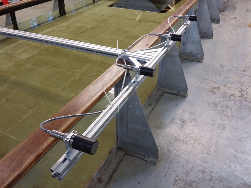
In addition to towing tank pressure pulse measurements, hydroacoustic measurements with a hydrophone line consisting of 16 individual hydrophones are carried out when the ship’s model is passing by [3]. To distinguish and localise sound sources, multiple hydrophones are arranged as an “acoustic camera”. This makes it possible to detect and analyse the noise generation at the bow of a model separately from the propeller-induced noise.
Furthermore, onboard measurements for different issues based on the full-scale ship are offered. In addition to underwater sound, far-field measurements with hydrophones from dinghy, as well as pressure pulse and acceleration measurements on the ship are possible.

Themenbezogene Referenzen/Forschungsprojekte
[1] Schulze, R.: Hydroakustik, 5. SVA-Forschungsforum, Potsdam, 26. Januar 2012
[2] Klose, R.; Schulze, R.: Körperschallmessungen zur Prognose kavitationsbedingter Erosion an Schiffspropellern, Kolloquium Kavitation und Kavitationserosion, Ruhr-Universität Bochum, 08./09. Dezember 2014
[3] Klose, R.; Schulze, R.: Körperschallmessungen zur Prognose kavitationsbedingter Erosion an Schiffspropellern, 8. SVA-Forschungsforum, Potsdam, 29. Januar 2015
[4] Schulze, R.: Messung des Propulsions- und akustischen Verhaltens am Heavy Lift Vessel „Anne Sofie“ von SAL, Ges. zur Förderung der SVA, Potsdam, 27. Juni 2014
Erosion Test
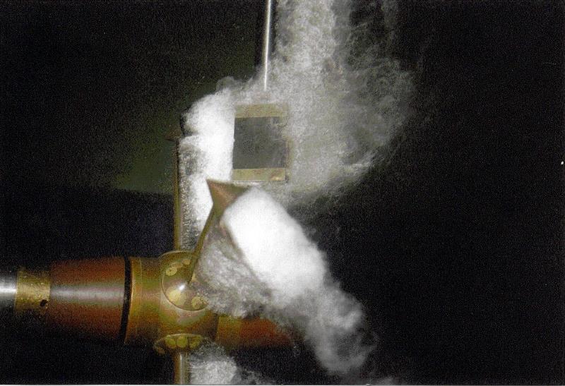
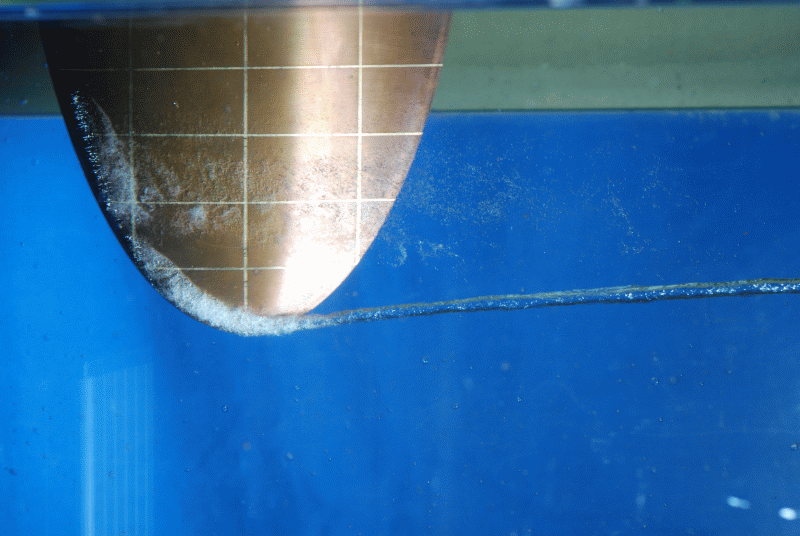
Cavitation erosion is a kind of material damage which is triggered by certain types of cavitation and can be responsible for deterioration in various areas. Due to the complexity of the process of cavitation erosion, the mechanism behind this action is not yet completely understood.
The risk of erosion of propellers, rudders or appendages is determined mainly by experiment. In the experiments, the erosive effect of the cavitation observed is evaluated and validated by Soft Surface Technique and / or acoustic measurements.
The basis for the erosion tests in the SVA were developed through various R & D projects. In collaboration with the Institute ZWFI “Akademik A.N. Krylov” in Leningrad the Soft Surface Technique was expanded into a method for predicting the erosion intensity [1]. Using this method along with a cavitation generator, parameters of propeller materials (erosion resistance) and erosion coatings were determined. With these values, through experiments, a statement about the risk of erosion and the erosion intensity can be made [2].
In cooperation with the Technical University of Dresden materials were investigated and theoretical methods [3] drawn up to enhance the understanding of the erosion mechanism.
Between 1999 and 2001, with funding from BMBF, the R & D projects “Investigating Layer, Bubble, and Cloud Cavitation and the Associated Erosion Problems” were conducted [4]. During the R & D projects, a new erosion coating was developed and tested in collaboration with the IFL Magdeburg.
Acoustics, which provides another possibility for erosion prediction, is currently being intensively researched as part of the R & D project KONKAV III [5]. Accordingly, erosive cavitation generates different frequency spectra than non-erosive cavitation. On this basis an erosion risk can be detected. The structure borne sound is measured right on the model propeller since the implosion of cavitation bubbles on its surface is responsible for erosion. This kind of erosion detection also offers interesting applications for the real ships on which cavitation monitoring in most cases is very difficult. Based only on the assessment of the frequency spectrum it is possible to determine, without much effort, whether the occurring cavitation is erosive or not.

Context Related References / Research Projects
[1] Selke, W., Mehmel, M.: Modellierung der Kavitationserosion an Propellern im Kavitationskanal, Seewirtschaft, 1 0(1978)4
[2] Georgijewskaja, E. P., Mawljudow, M. A.; Mehmel, M.: Entwicklung einer Methode zur Vorhersage der Kavitationserosion an Schiffspropellern, Schiffbauforschung 3(1981)
[3] Bux, K.: Theoretische und experimentelle Analyse der erosiven Wirkung kavitierender Strömungen auf metallische Werkstoffe, Dissertation, Technische Universität Dresden 1987
[4] Heinke, H.-J.: Untersuchung von Schicht-, Blasen- und Wolkenkavitation und der damit verbundenen Erosionsprobleme, 23. BMBF- Statusseminar Entwicklung in der Schiffstechnik, 18. Oktober 2000, Rostock
[5] Klose, R., Schulze, R.: Körperschallmessungen zur Prognose kavitationsbedingter Erosion an Schiffspropellern, Kolloquium Kavitation und Kavitationserosion, Ruhr-Universität Bochum, 08./09. Dezember 2014
[6] Klose, R., Schulze, R.: Körperschallmessungen zur Prognose kavitationsbedingter Erosion an Schiffspropellern, 8. SVA-Forschungsforum, Potsdam, 29. Januar 2015
Pressure Fluctuation Measurement
Besides the main engine, the propeller is the primary cause of ship vibrations. Regarding the formation of the propeller-induced vibrations, two mechanisms of action can be distinguished:
- Through the work of the propeller in the irregular wake field, periodically fluctuating forces and moments occur which are introduced via the shaft bearings in the hull.
- The propeller, with its rotating pressure field, generates pulsating compressive forces on the hull. Through the work of the propeller in the irregular wake field additional periodic pressure pulses arise, which can be significantly increased by temporarily occurring cavitation at the propeller blade.
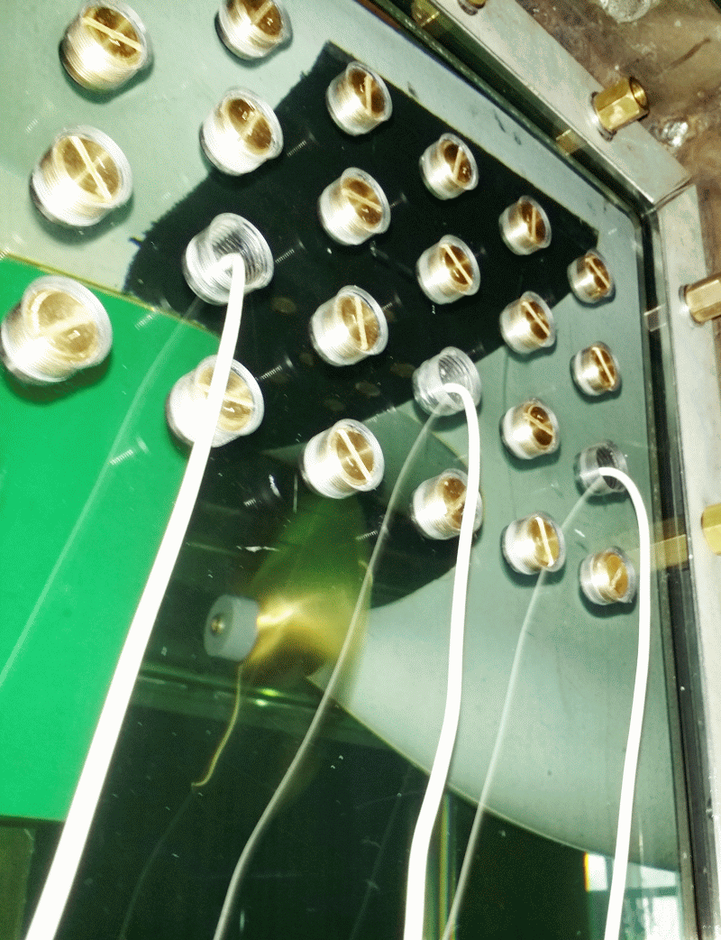
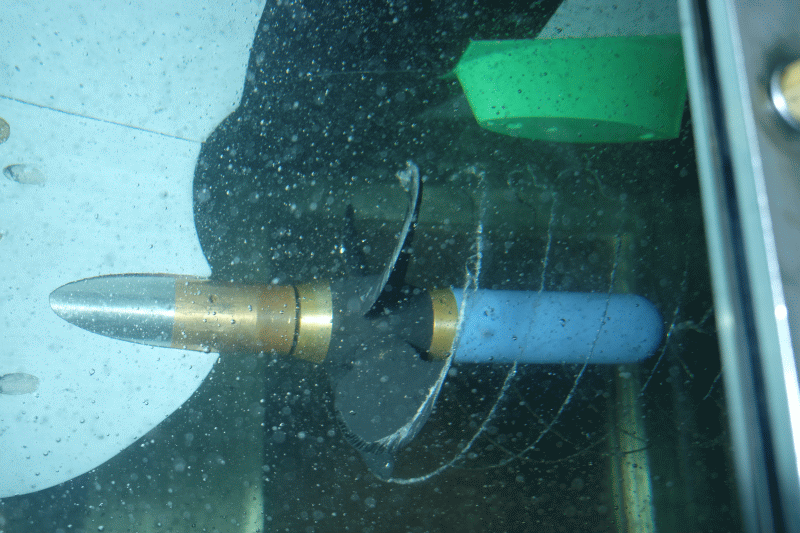
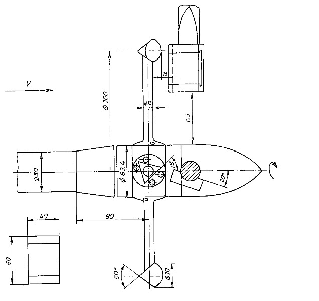
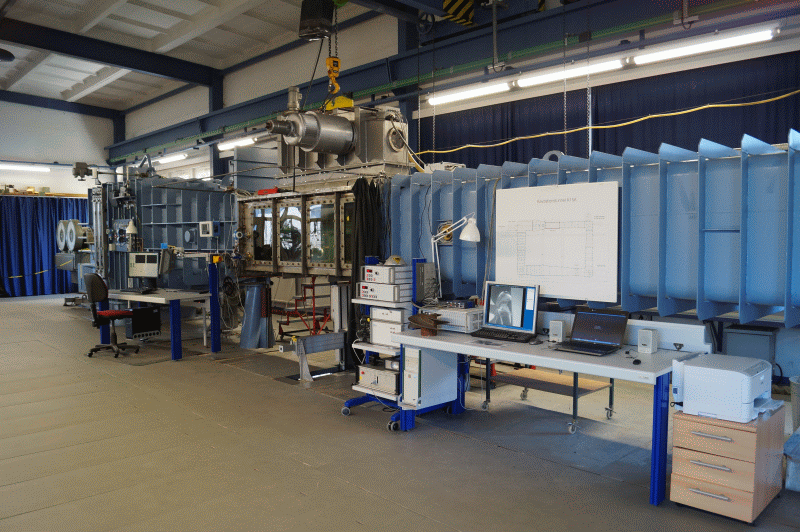
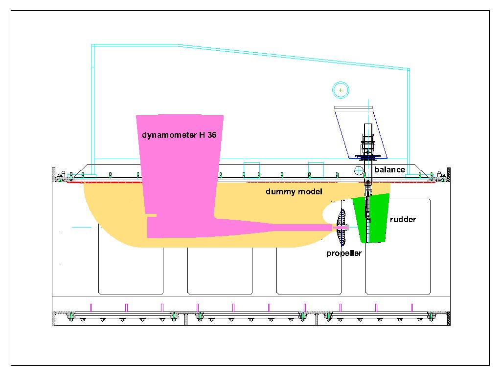
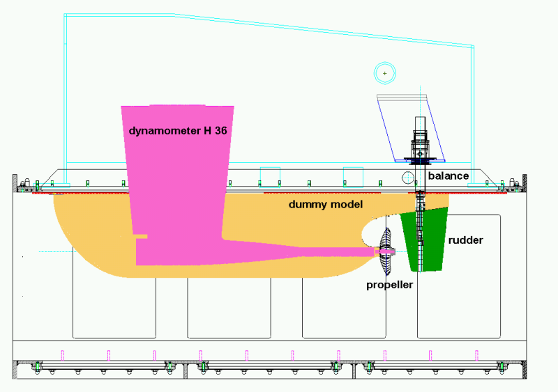
The measurement of the pressure pulses induced by the propeller on the hull of the vessel is accomplished in the large test section (2600 mm x 850 mm x 850 mm) of the cavitation tunnel K15A from Kempf & Remmers [1], [2], [3]. A typical experimental setup for propeller ships is shown. The propeller is driven by the dynamometer H36. Up to 16 pressure sensors are positioned above the propeller in the stern of a dummy model. The length of the dummy models (shortened models with stern contours to scale), is between 2.2 and 2.7 meters. With the dummy model, the predicted three-dimensional inflow to the propeller at the Reynolds number of the vessel is simulated. Within the framework of R & D projects or, for comparison with measurements on ship models, the wake field distribution of the model can be simulated.
Cavitation trials and pressure pulse measurements are based on systematic series of experiments and full-scale measurements to determine and compare the influence of various parameters. The experiments are carried out at high rotational speeds of the propeller model (n > 25 s-1). The oxygen content of the water as a measure of the gas content of the water is controlled at a saturation degree of α / αS > 60%, in order to minimize the influence of the nuclei content of the water and thus the scale effects on the cavitation. In addition, the pressure pulse measurements are performed according to predefined test procedures which, among other things, include a run-in phase of the testing equipment of at least an hour and a range of additional measurements with variations of propeller load and cavitation numbers and variations of the experimental parameters.
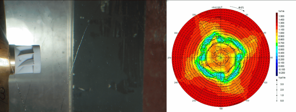
The prognosis and simulation of the inflow at the propeller according to the conditions on the ship is a central point of the R & D work on the development of experimental methods for cavitation trials and pressure fluctuation measurements [4], [5]. Therefore, in preparation for the measurements, CFD calculations are performed for the flow around the ship as well as for the flow around the model. Before carrying out the cavitation and pressure pulse measurements, the velocity distribution in the propeller plane of the dummy model will be measured with the LDV system.
Context Related References / Research Projects
[1] Selke, W.; Heinke, H.-J.: Propelleruntersuchungen im Kavitationstunnel der Schiffbau-Versuchsanstalt Potsdam, STG-Jahrbuch 1990
[2] Schmidt, D.; Selke, W.; Gerchev, G.: Comparative Joint Investigations in the Cavitation Tunnels of SVA and BSHC on the Prediction of Propeller Induced Pressure Pulses, Schiffbauforschung 31/1, 1992
[3] Heinke, H.-J.: The Influence of Test Parameters and Wake Field Simulation on the Cavitation and the Propeller Induced Pressure Fluctuations, Jahrbuch der Schiffbautechnischen Gesellschaft, 97. Band, 2003
[4] Heinke, H.-J.; Hellwig-Rieck, K.: Investigation of Scale Effects on Ships with a Wake Equalizing Duct or with Vortex Generator Fins, Second International Symposium on Marine Propulsors, smp’11, Hamburg, Germany, June 2011
[5] Kleinwächter, A.; Hellwig-Rieck, K.; Ebert, E.; Kostbade, R.; Heinke, H.-J.; Damaschke, N. A.: PIV as a Novel Full-Scale Measurement Technique in Cavitation Research, Fourth International Symposium on Marine Propulsors, smp’15, Austin, Texas, USA, June 2015
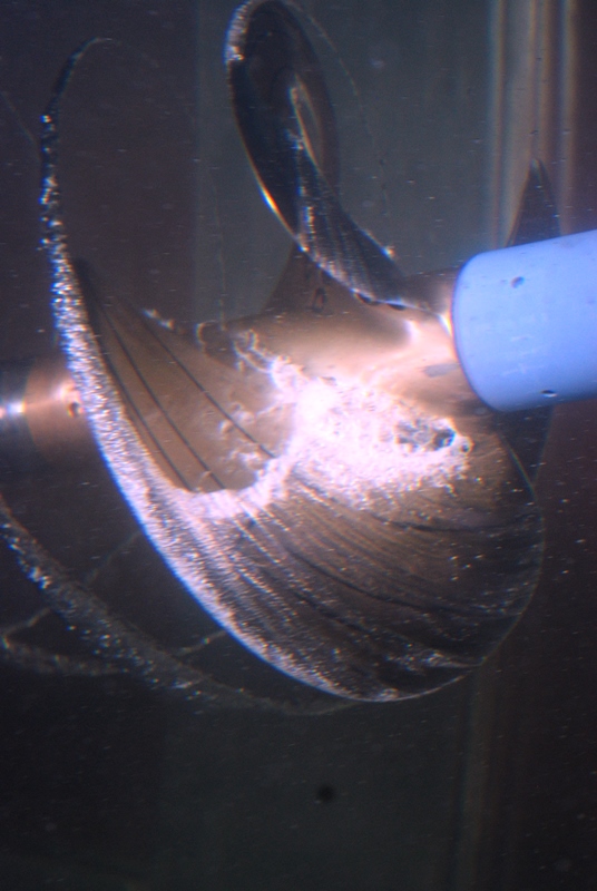
Cavitation Test

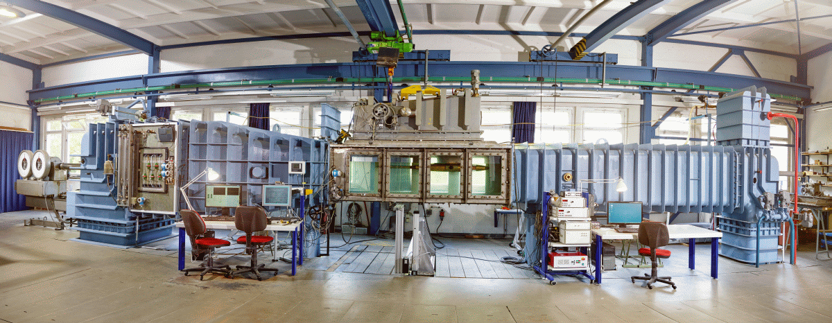
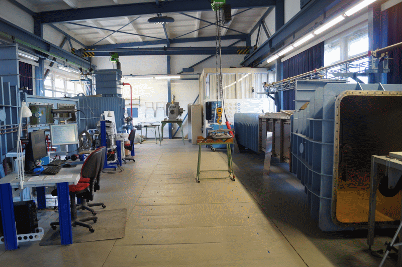
Cavitation tests are carried out in the cavitation tunnel K15A from Kempf & Remmers. The cavitation tunnel has two test sections with cross sections 600 mm x 600 mm and 850 mm x 850 mm and a length of 2.60 m. In the small test section, cavitation tests are predominantly performed with propellers for fast ships and special tests such as measurements on profiles and wings, speed measurements with LDV or PIV, erosion tests, and calibrations of speed measurement systems.
The investigation of the behaviour of propeller cavitation in the wake field of a vessel and measurement of propeller-induced pressure pulses [2] – [6] are carried out in the large test section of the cavitation tunnel. The typical experimental setup for a single-screw vessel is shown in the schematic diagram. The propeller is driven by the dynamometer H36 by Kempf & Remmers. The simulation of the wake, calculated for a Reynolds Number of the full-scale ship, is done with a dummy model and additional grids. The dummy models are up to 2.60 m long and geometrically similar to the ship in the stern area. The blocking of the measuring cross section is within the range between 10 to 22 %. High-Speed recordings of cavitating propulsion systems can be found here.
Context Related References / Research Projects
[1] Potsdam Propeller Test Case: https://www.sva-potsdam.de/en/potsdam-propeller-test-case-pptc
[2] Schmidt, D.: Propellererregte Druckschwankungen an Frachtschiffen mit großen langsamlaufenden Propellern, Schiffbauforschung 26 (1987) 3
[3] Selke, W., Heinke, H.-J.: Propelleruntersuchungen im Kavitationstunnel der Schiffbau-Versuchsanstalt Potsdam, Jahrbuch der STG, 84. Band, 1990
[4] Schmidt, D., Selke, W., Gerchev, G.: Comparative Joint Investigations in the Cavitation Tunnels of SVA and BSHC on the Prediction of Propeller-Induced Pressure Pulses, Schiffbauforschung 31(1992)1
[5] Heinke, H.-J.: Einfluss des Nachstroms auf die Kavitation und Druckschwankungen eines Propellers, 13. SVA-Forum, Potsdam, 29. August 2006
[6] Heinke, H.-J.: The Influence of Test Parameters and Wake Field Simulation on the Cavitation and the Propeller Induced Pressure Fluctuations
Jahrbuch der Schiffbautechnischen Gesellschaft, 97. Band, 2003