Author: pa

Podded Drives

SSPCFK Propeller Pod in Cavitation Tunnel

The main feature of podded drives is the integration of a powerful electric drive in a hydrodynamically optimised pod beneath the ship which drives the propeller directly. The full power can be used in any azimuth direction (0 – 360).
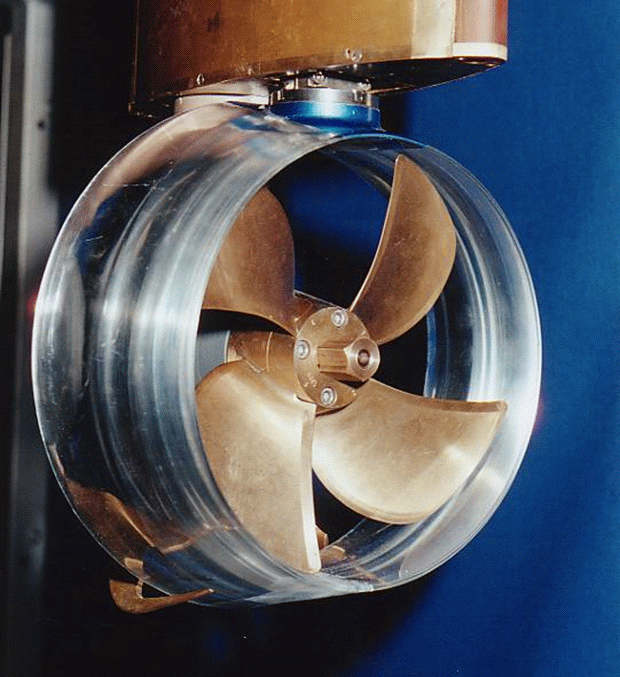
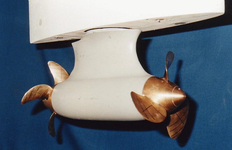
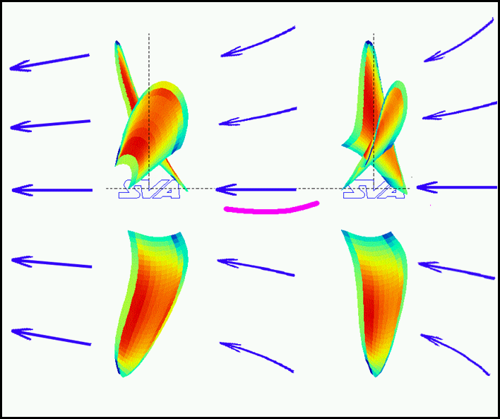
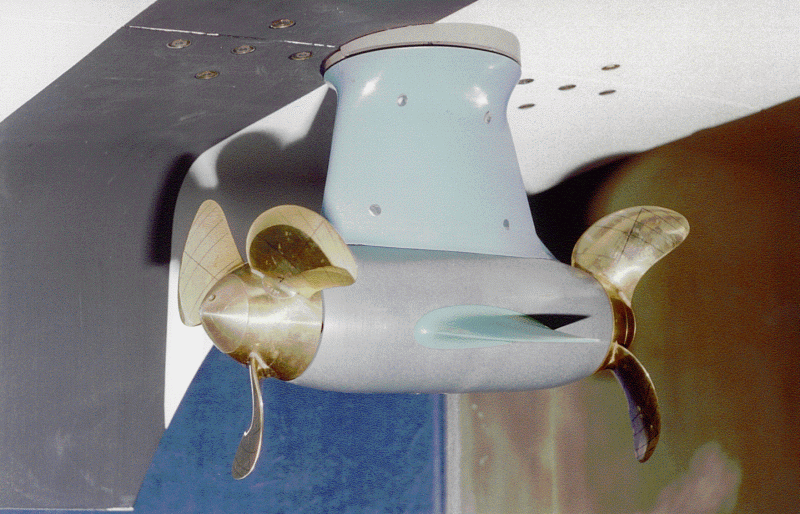
The podded drive is a propulsion system comprised of the components propellers and pod housing. The development and optimisation of podded drives requires knowledge of the interaction between propeller and pod housing and about the influence of design parameters on the characteristics of the system.
SVA Potsdam has been working in the field of podded drives since 1995 [1], [2]. Among other studies, the applicability of podded drives, dynamic flow calculations, analyses of various podded drives as well as numerous model studies have been performed there [3], [4], [8]. Developments for podded drives were conducted in collaboration with various manufacturers [3], [9].
As part of a BMWi funded project “Integrated Ship Design for Ships with Podded Propulsion Systems”, aspects of ship design for ships with podded drives were examined. In the BMWi funded project “High-Speed Pod”, concepts for podded drives with application speeds up to 30 knots were developed and studied experimentally and computationally [5], [6]. The ideas and findings resulting from these projects were the basis for the development of High Efficiency Pods with HTS technology [9].
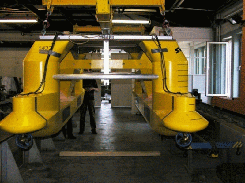
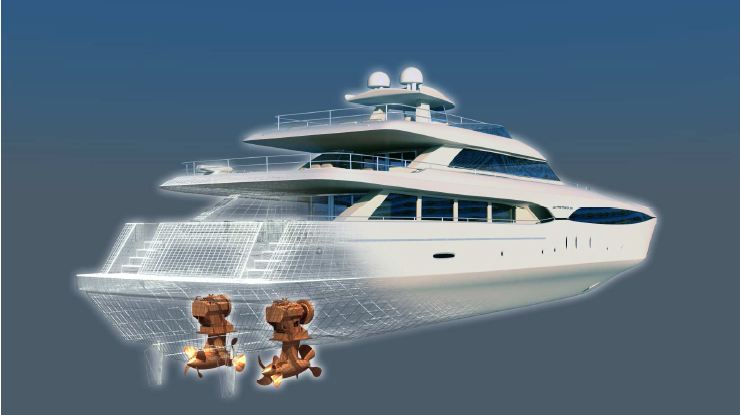
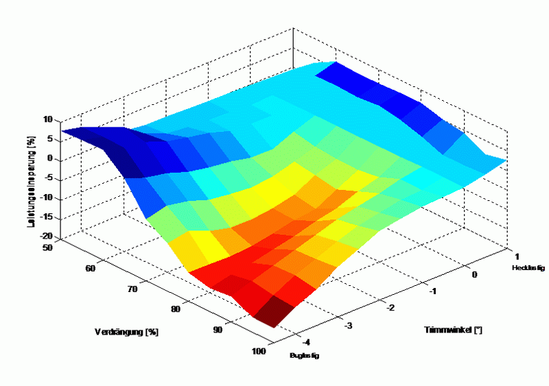
The manoeuvrability of propulsion systems with podded drives were examined as part of a BMBF funded project [7]. The arrangement of the pod at the stern of the ship, the use of fins, and the influence of the propeller assembly were analysed experimentally and computationally.
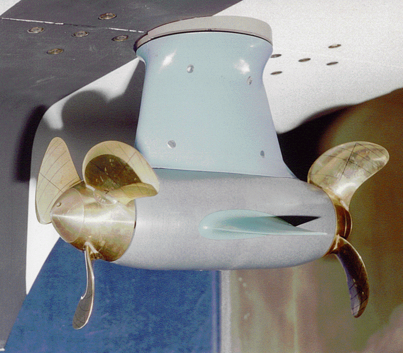
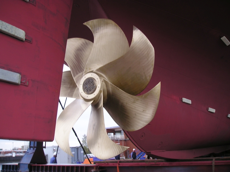
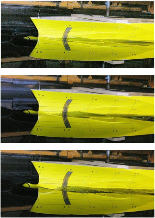
Standard podded drives with pull and push propeller variants have been developed and investigated experimentally [6], [8], [9]. The pod housings (gondolas) were particularly varied with regard to the gondola diameter and the transition from the propeller to the gondola in order to determine the influence of geometric parameters on the characteristics of podded drives (open water, propulsion, cavitation).
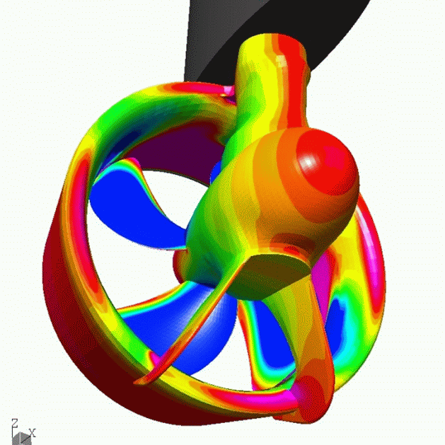
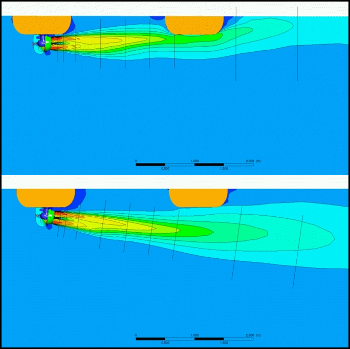
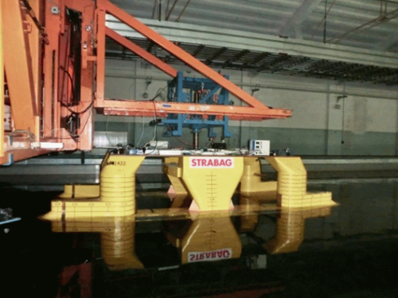
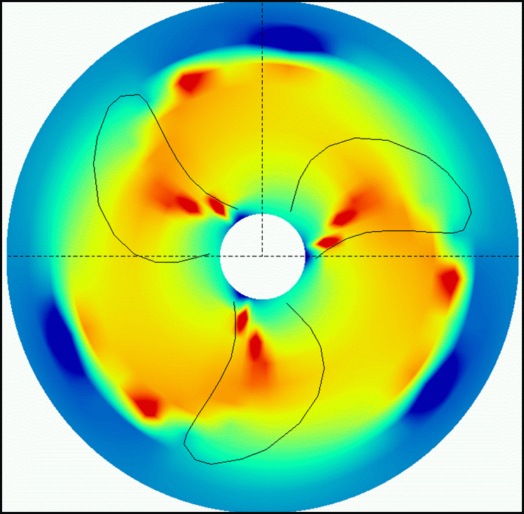
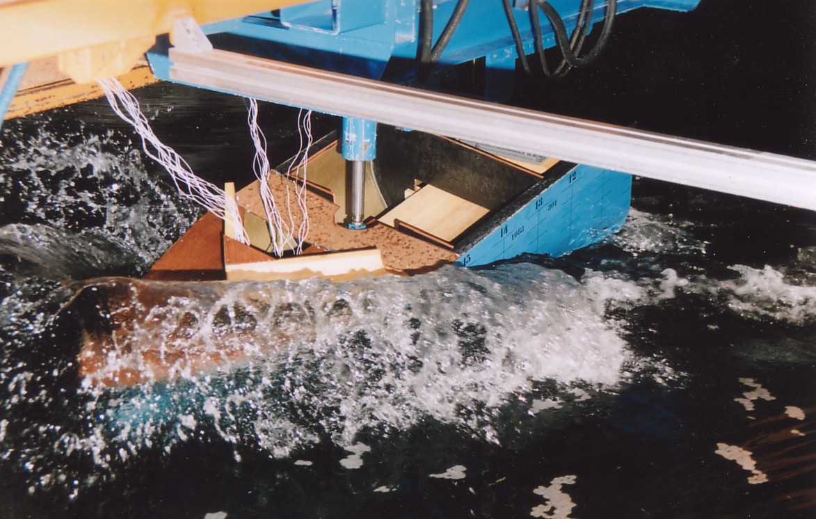
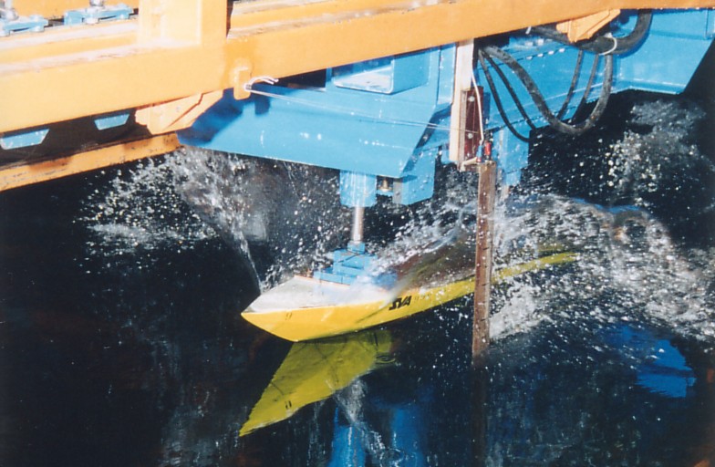
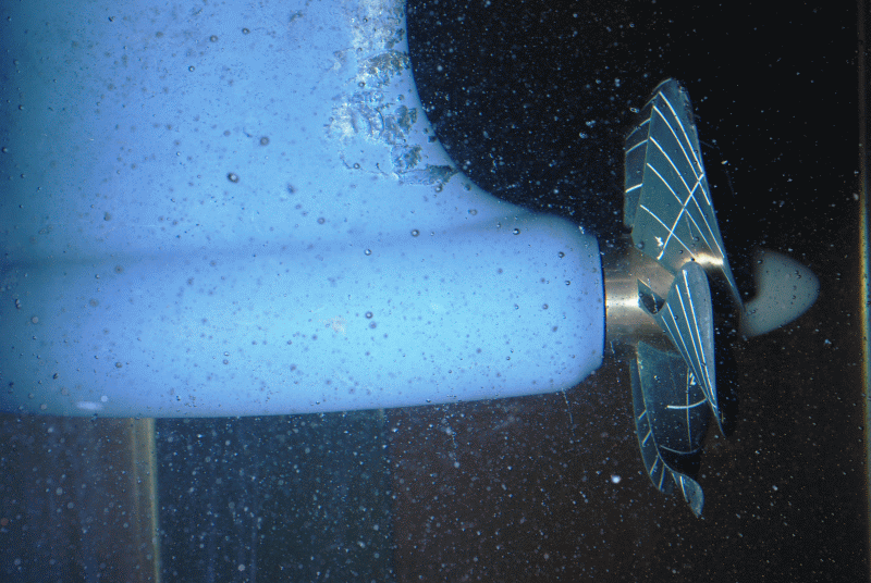
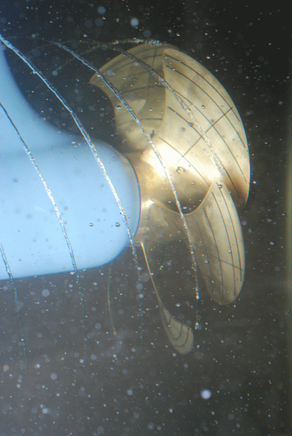
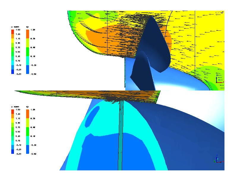
The development and the study of podded drives places high demands on measurement technology and experimental methods. For open water, propulsion and cavitation measurements, manoeuvring and speed measurement systems on podded drives have been developed, tested and used successfully. To validate the evaluation and forecasting methods for measurements with podded drives, CFD calculations were performed.
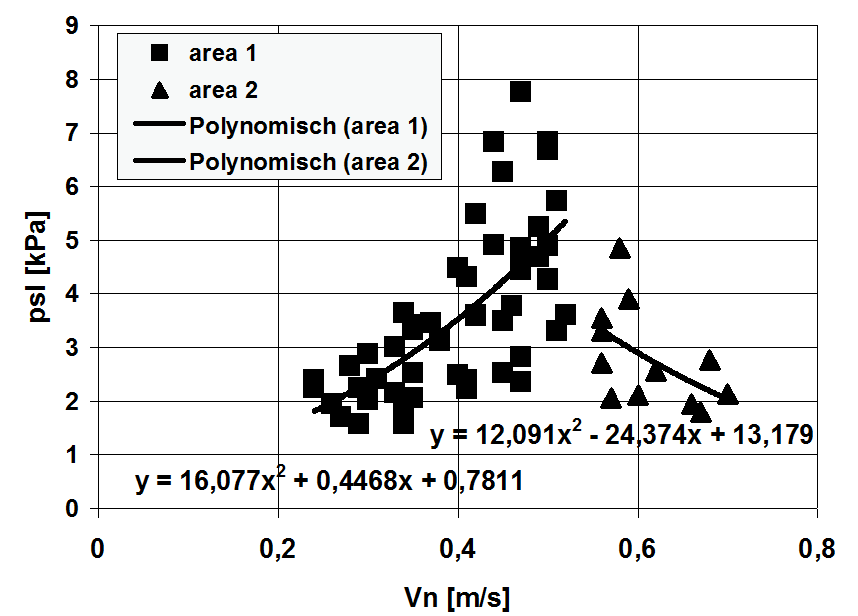
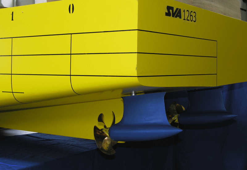
With the available azimuth measuring systems for podded drives, pull, push, twin, and counter-rotating propeller assemblies can be analysed. Among other things, the thrusts and moments of the propeller are measured in the shaft and the lateral and vertical forces can be measured at the housing.

Pods_Galerie_KT_HSP_im_ Kavitationsversuch

Pods_Modell_mit_Pods_small

Pods_u_p_HTS1A_VP1357

Pods_u_p_HTS1C_VP1357


Context Related References / Research Projects

[1]    Heinke, H.-J.: Azimuthing propulsion – Experiences of SVA, 6th SVA-Forum “Azimuthing Propulsion – new challenges and chances”, Potsdam, 29th April 1998
[2]    Abdel-Maksoud, M., Heinke, H.-J.: Investigation of Viscous Flow Around Modern Propulsion Systems, CFD ’99, The International CFD Conference, 5-7 June 1999, Ulsteinvik
[3]    Kaul, S., Heinke, H.-J.; Abdel-Maksoud, M.: Hydrodynamische Optimierung von Podded Drives und aktuelle Anwendungen in der Großausführung, 54. Sitzung des FA „Schiffshydrodynamik“ der STG, Hamburg, September 2000
[4]    Heinke, H.-J.: Kavitationsuntersuchungen zu Podded Drives, 20. Strömungstechnische Tagung des Instituts für Strömungsmechanik der TU Dresden, 6. Oktober 2000
[5]    Heinke, H.-J.: Alternative Propulsion Concepts for Fast Navy Ships, Part II: Podded drives for navy ships,  International Lecture Day “Unconventional Hull Forms for Naval Vessels”, Potsdam, September 2001
[6]    Heinke, C., Heinke, H.-J.: Investigations about the Use of Podded Drives for Fast Ships, FAST 2003, Ischia (Italy), Oct. 2003
[7]    Steinwand, M.: Manoeuvrability of a Single Screw Ship with Pod, Hydronav’2003, Gdansk, Poland, Oct. 2003
[8]    Heinke, H.-J.: Investigations about the forces and moments at podded drives, First International Conference on Technological Advances in Podded Propulsion, Newcastle, UK, April 2004
[9]    Heinke, H.-J.: Hydrodynamische Untersuchungen für einen Podded Drive mit HTS-Synchronmaschine, Statustagung Schifffahrt und Meerestechnik, Bundesministerium für Wirtschaft und Technologie, 3. Dezember 2009, Rostock-WaPartner

Thruster

Thruster_Schottel_RuderpropThruster_Schottel_Ruderprop_CFD

Thrusters are propulsion systems used for ships and platforms where manoeuvrability is an important criterion. Thrusters can usually swivel 360° so that the system can act in any direction. The propeller works in front of or behind the housing (pull and push) which results in strong interactions between the propeller and the housing. Experimental and numerical investigations of thrusters are conducted because of these interactions and also special operating conditions such as bollard pull, manoeuvring, off-design, which are more demanding than conventional propellers. When analysing thrusters mostly open water propulsion and cavitation tests are carried out.

Special propulsion and measuring systems have been developed for the study of thrusters. The SVA owns propulsion and measuring systems for use in the towing tank and cavitation tunnel for testing thrusters with pushing or pulling propellers, twin and also contra rotating propellers. The systems allow the measurement of thrusts and moments of the propellers and the determination of housing resistance. The system forces and torques of the thruster are measured with 3- or 6-component balances.

Tests and calculations for thrusters are carried out in particular for propeller manufacturers (determination of the characteristics of thrusters, optimisation and development), shipyards and shipping companies (Propulsion). To convert the model test results to full-scale, the SVA has developed its own method for Reynolds number correction for thrusters. Systematic CFD calculations of thrusters were carried out in the R & D project “Correlation of Z-Drives with Ducted Propellers” [2], [4].

In recent years, aspects of DPability of thrusters were increasingly analysed. As part of the research project “Thruster for Dynamic Positioning” [5], [6] extensive studies on the influence of gondola and nozzle angle on the operating parameters of the thruster, the interaction of the thruster with the platform, and the mutual interaction of the thrusters were performed.

For the study of DP capability of platforms, special propulsion and measuring systems have been developed to ensure the variability of the inclination of the gondola housing and an unlimited pivoting of the thruster.

Thruster_CFD_PlatformThruster_Offshore_PlatformThruster_Offshore_Platform_in_SR


Context Related References / Research Themes

[1] Abdel-Maksoud, M., Heinke, H.-J.: Investigation of Viscous Flow around Modern Propulsion Systems, CFD’99, Ulsteinvik, Norway, June 1999
[2] Abdel-Maksoud, M., Heinke, H.-J.: Scale Effects on Ducted Propellers, 24th Symposium on Naval Hydrodynamics, Fukuoka, Japan, July 2002
[3] Heinke, H.-J.: Azimuthing propulsion – Experiences of SVA, 6. SVA – Forum „Azimuthing Propulsion – new challenges and chances“, Potsdam, April 1998, Schiffbauforschung 38 (1999) 1
[4] Heinke, H.-J., Abdel-Maksoud, M., Pierzynski, M. (2006): Korrelation Z-Antrieb mit Düsenpropeller, Schiff & Hafen, 2006, Heft 5
[5] Heinke, H.-J.: Model Tests with the Voith Radial Propeller, 3rd Hydrodynamic Symposium on Voith Schneider Propulsion, Heidenheim, June 2010
[6] Heinke, C.: Erhöhung der DP-Fähigkeit durch optimalen Einsatz von Thrustern, STG-Hauptversammlung, Hamburg, November 2012, Jahrbuch der Schiffbautechnischen Gesellschaft, 107. Band, 2012

Twin and Contra-rotating Propellers

TwinProps_GegenlaufProp_im_Versuch

FORTJES in the stern of a pleasure boat

Twin propellers

Twin propellers work with a pull and a push propeller with the same rotational direction. The design of the rear propeller places increased demands on the calculation method. Twin propellers should be arranged such that the vortex of the pulling front propeller passes between the wings of the rear pushing propeller. By the contraction of the propeller wash of the pulling propeller, additional water from the sides reaches the pushing propeller.

If twin propellers are used on thusters (Schottel Twin Propeller (STP)), or Podded Drives (Siemens Schottel propulsor (SSP)), the housing must be hydrodynamically optimised and provided with guide fins. The twist in the propeller wash of the pulling propeller is partially recovered in this way and influences the inflow to the targeted pushing propeller.

The SVA‘s VORTEX propeller calculation method has been adapted for the design and optimisation of twin propellers [1]. The following photos show examples of the hydrodynamic model and the calculated inflow to a pushing propeller.

Contra-rotating Propeller

Contra-rotating propellers consist of two contra-rotating propellers. Through the reverse rotating propeller, rotational losses can be avoided because the rear propeller can use the rotational energy of the flow which is induced by the forward propeller. In addition, the load is distributed over the two propellers.

The SVA has measuring systems for the study of contra-rotating propeller systems in both the towing tank and cavitation tunnel. In recent years systematic studies of the effect on efficiency of the distance between the contra-rotating propellers and the layout of pods between the contra-running propellers have been carried out.

On behalf of REINTJES, the Fortjes® pod propulsion system was developed [5], [6]. The propulsion system is used especially in planing and semi-planing yachts up to 40 m long and in a power range of up to 3000 kW. The SVA’s VORTEX method was and is used for the design of contra-rotating propellers. Gondola and shaft were completely newly designed to optimally take advantage of the contra-rotating propeller and the pod.


TwinProps_GegenlaufPropTwinProps_HydrodynModell_CFD_mRandTwinProps_Zuströmung_CFD_mRand
TwinProps_SchottelTwinProp_mRandTwinProps_SSP_im_Versuch


Context Related References / Research Projects

[1] Schulze, R.; Bertolo, G.; Brighenti, A.; Kaul, S.: LUITO Development and Optimisation of the Propulsion System; Study, Design and Tests, PRADS, The Hague, September 20 – 25, 1998
[2] Kaul, S.; Heinke, H.-J.; Abdel Maksoud, M.: Hydrodynamische Optimierung von Podded Drives und aktuelle Anwendungen in der Großausführung (Anwendungsbeispiele SSP), 54. Sitzung des FA „Schiffshydrodynamik“ der STG, Hamburg, 13.09.2000
[3] Edel, K.-O.: Zum Entwurf gegenläufiger Propeller nach der Theorie von Lerbs (77. Mitteilung der SVA), Schiffbauforschung 10 (1971) 5/6
[4] Schmidt, D.: Propulsionsuntersuchungen mit Einzelpropeller und Gegenlaufpropeller am Modell eines Containerschiffes, Schiffbauforschung 14 1/2/1975
[5] Schulze, R.; Weber, A.: Application of the new FORTJES® Z-drive from REINTJES on planing vessels, 11th Intern. Conference on Fast Sea Transportation, FAST 2011, Honolulu, Hawaii, USA, Sept. 2011
[6] Schulze, R.; Weber, A.: The new FORTJES® Z-drive from REINTJES with contra rotating propellers for high speed applications, 11th Intern. Conference on Fast Sea Transportation, FAST 2011, Honolulu, Hawaii, USA, Sept. 2011

Design of Propellers and Propulsion Systems

Propeller_Solea

Propentwurf_Prop_m_asym_Ruder

The SVA has a long and diverse experience in the field of propeller design and the design of complex propulsion systems. As a model basin and research institute, the SVA Potsdam has the unique advantage of being able to use the experience gained from basic and applied research directly for the design of propulsion systems.

Major parts of design programs have been developed in the SVA. This includes pre-processing for propeller definition and geometry modification and recalculation processes for propellers, ducted propellers, twin and contra-rotating propellers. Furthermore, mathematically based optimisation methods and post-processing for assessment of cavitation, pressure fluctuation predictions and strength calculations using FEM analysis, and interfaces for 3D modeling are included. All of these programs are contained within the program package of VORTEX. Other propeller manufacturers and classification societies use, among other things, this software for design and certification. The continuous development of design tools is supported through close contact with these propeller manufacturers and classification societies.

The SVA has had, among other things, significant contributions to the development of the twin propeller concept from SCHOTTEL and set milestones in the development of low-noise propellers for research, naval vessels and submarines. For large tug boats, ducted propellers are designed with more than 200 t thrust. In the development of ducted propellers with high static thrust demands in particular, the broad experience with extensive CFD calculations of propulsion systems on the ship can be made use of.

Designs of propellers and propulsion systems can be fully tested in the SVA in model scale, whereupon despite advanced calculation methods, model testing cannot be dispensed with. After propulsion or cavitation testing, the propeller design can be improved to meet the highest standards of practice.

To determine the behaviour of ship and propulsion system and the tuning of the engine, trial runs are accompanied by the SVA during which special full-scale measurements (power measurement, vibration, pressure fluctuations and acoustics measurements, cavitation observations, manoeuvring measurements) are conducted.


Context Related References / Research Projects

[1] Schulze, R.: Globale Optimierung von Propellern, STG-Sprechtag, Flensburg 14. März 1997
[2] Schulze, R.; Bertolo, G.; Brighenti, A.; Kaul, S.: LUITO Development and Optimisation of the Propulsion System; Study, Design and Tests
PRADS, The Hague, September 20 – 25, 1998, 1998 Elsevier Science B.V.
[3] Schulze, R.: Globale Optimierung von Propellern und Propulsionssystemen, Schiff & Hafen 3/2005
[4] Mertes, P., Heinke, H.-J.: Aspects of the Design Procedure for Propellers Providing Maximum Bollard Pull, ITS 2008, Singapore, May 2008
[5] Steinwand, M.; Grabert, R.; Schulze, R.: Ruderentwurf – Aktuelle Entwicklungen, 102. STG Jahreshauptversammlung, Berlin, 23. Nov. 2007
[6] Schulze, R.; Richter, H.: Redundante Antriebe für Einschraubenschiffe, 102. STG Jahreshauptversammlung, Berlin, 23. Nov. 2007
[7] Schulze, R., Weber, A.: Application of the new FORTJES&rmark; Z-drive from REINTJES on planning vessels; 11th Intern. Conference on Fast Sea Transportation, FAST 2011, Honolulu, Hawaii, USA, Sept. 2011
[8] Schulze, R., Weber, A.: The new FORTJES&rmark; Z-drive from REINTJES with cotra rotating propellers for high speed applications, 11th Intern. Conference on Fast Sea Transportation, FAST 2011, Honolulu, Hawaii, USA, Sept. 2011
[9] Heinke, H.-J., Lübke, L. O.: Maßnahmen zur Energieeinsparung, Schiff & Hafen 10/2014

Trim Optimization

Trimmopt_DiagrammTrimmopt_Schiff

The trim of a ship influences the power consumption. Through an optimal trim several percent power savings can often be achieved.

Trim optimisation tests have already been carried out as standard procedure since 1970. As a result of the R & D project “Effective Trim Optimisation for Cargo Ships” [1] it has been possible to improve the predicting methods of power savings (calculated trim optimisation) as well as the experimental trim optimisation. The methods have different approaches from a purely statistical analysis of extensive model test series up to CFD simulations of entire trim matrices:

  • Prediction of the resistance of the ship for different draughts with or without combinations of various trim states using the resistance method according to Danckwardt and / or the SVA-LSR method
  • Formulas for determining the influence of partial discharging and / or trimming characteristic values on the propulsion
  • Hybrid procedure: Predicting of resistance and propulsion for partial discharging and / or trimming by coupling parts of the process of resistance according to Danckwardt / SVA LSR method with experimental results
  • Trim optimisation through pilot projects (EFD)
  • Trim optimisation through CFD calculations (CFD)

As a result, master and officers may set the optimum trim condition for the ship using the information provided by the methods mentioned above. The 3D contour plot shows an example of the dependence of the power saving on displacement and trim.


Context Related References / Research Projects

[1] Heinke, C.: Effektive Trimmoptimierung für Frachtschiffe, Bericht 4394, Schiffbau-Versuchsanstalt Potsdam GmbH, Juni 2015, Abschlussbericht

Slamming

Slamming_Diag

Slamming_Modell_alt

Slamming_Modell_neu

For slamming tests, a hydraulic slamming simulator was developed in the SVA. With the help of this system, the model is made to heave and pitch and produce coupled motions using two longitudinally arranged, vertically movable, hydraulic pistons. Depending on the model size, amplitudes up to 0.1m are reached at frequencies up to 2Hz. Thus slamming loads can be simulated, in which the critical immersion speeds are significantly exceeded. Both hull slamming of planing boats and bow flare slamming on all types of vessels with significant bulkhead failure are examined primarily in the bow area. The system allows the simulation of regular and irregular movements. The advantages over slamming measurements in a conventional sea state tests of the targeted replication of slamming scenarios is that defined immersion conditions can be assigned, and also in the exact reproducibility of the experimental conditions.

The equiping of models with miniature pressure sensors of different sizes allows the measurement of slamming pressures on vulnerable positions of the hull in the model test under extreme sea conditions, both when driving and when stationary. Moreover, slamming pressures can also be measured with regular seakeeping tests.

Slamming phenomena are also simulated with existing CFD tools. The UTHLANDE program serves to determine slamming prevalence. For a quick estimate of slamming pressures the SVA has developed a simplified procedure. It is based on results of systematic model tests and allows the determination of slamming pressure for any hull shape, for a given speed and location on the vessel. An important parameter is the velocity normal to the hull and the fluid at the point of interest of the hull surface. Areas with air entrapment (hull slamming) can therefore not be detected.

As a result, the processing of various R &  D projects [1], [2], the [3] SVA has a wealth of experience in investigating slamming phenomena.


Context Related References / Research Projects

[1] Fröhlich, M.: Einsatz eines Schwingungsoszillators auf hydraulischer Basis zur Untersuchung der Slammingbelastung von Schiffen, STG-Sprechtag „Schiffe im Seegang“, Hamburg, Oktober 1998
[2] Fröhlich, M.: Slammingbelastungen von Schiffen, Freitagsvorlesung an der TU-Berlin, 25.06.99
[3] Fröhlich, M.; Hellwig, K.: Numerical and experimental investigations of slamming loads for fast ships, HIPER`01, Hamburg May 2001
[4] Fröhlich, M.; Hellwig, K.: Untersuchungen zum Slammingverhalten schneller Schiffe, 6. Schiffbautag Mecklenburg-Vorpommern, Rostock, Oktober 2002