Author: pa

Wave Energy Conversion

Lorem ipsum dolor sit amet, consectetur adipiscing elit. Curabitur lectus elit, porttitor quis placerat eget, porttitor eget nunc. Aliquam vel ex lectus. Sed ultricies sed nisi vitae faucibus. Integer sit amet dapibus dolor. Proin tincidunt orci a neque convallis tincidunt. Sed consectetur vel ex sit amet euismod. Praesent commodo ex id ligula porttitor semper. Morbi tempus justo id nisl mattis, eu laoreet sapien suscipit. Aenean est lacus, sodales nec varius vel, convallis sit amet nisl. Cras eleifend, ante vel tempus aliquam, tellus orci tristique nisl, nec convallis diam metus at diam. Proin egestas mauris ligula, in elementum ex efficitur eget. Praesent viverra commodo lacus, eget molestie dui molestie sed. Aliquam nec mollis quam. Phasellus euismod consectetur tincidunt. Phasellus sit amet felis elementum, bibendum dolor quis, blandit magna.

Curabitur eu massa vitae turpis laoreet molestie in eu velit. Nunc in condimentum nisl. Suspendisse potenti. Nullam ante ex, varius nec dignissim faucibus, suscipit vel eros. Aliquam condimentum nisi sit amet est vestibulum tincidunt. Quisque nisl enim, tempor in porttitor sed, ornare ac massa. Mauris sed convallis nisl. Aenean volutpat finibus turpis. Ut porta sagittis ligula congue vestibulum.

Dynamic Positioning Calculation

DP_Sims_bild1b_small

Keeping the position of a ship, regardless of sea state, wind and current is called “Dynamic Positioning” (DP). For offshore vessels and platforms DP capabilities are critical to executing their missions at any time. When designing these systems, knowledge of the forces acting on the ship is required in order to interpret or control the DP-drive systems. At SVA Potsdam, these forces are determined with experimental methods and also by mathematical means.

  • Wind Forces
  • Wave Forces
  • Current Forces

Each of these forces is determined seperately and the total resulting force is then calculated by the principle of superpostion.

  • Wind forces are calculated using empirical formulas, usually according to Blendermann [1] or Isherwood [2]. The calculation of wind forces can be carried out for any surface vessel.
  • The wave forces are calculated with the program system UTHLANDE. These calculations are based on linear strip theory. The drift forces are determined for each given sea state.
  • The values for current forces are obtained from the SVA’s extensive database of comparative ships. Moreover, the results come from the SVA research project “Determination of Forces and Moments on The Hull at Angles of Incidence through 360°” into the forecasting methods of SVA.

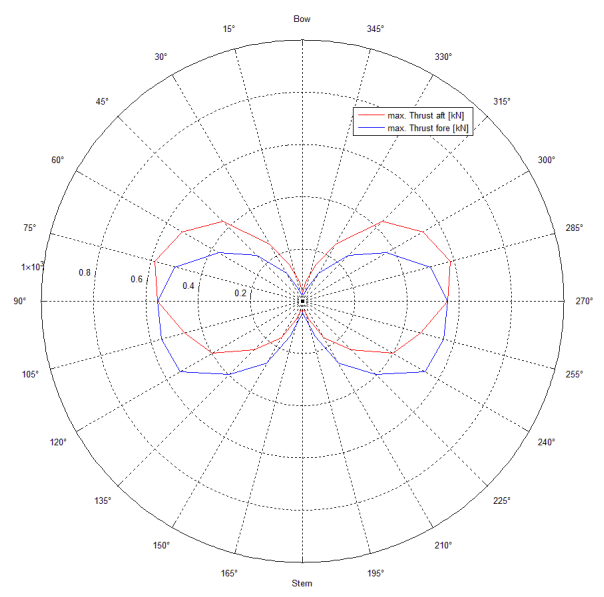
As a result, DP Capability plots come for the various scenarios and environmental conditions studied. The example below shows a single DP Capability Plot for a ship with bow and stern thrusters. The forecasting provides the needed thrusts of the particular thruster, which are necessary for the investigated combination of waves, wind and current to hold the ship in position.


Context Related References / Research Projects
[1]    Blendermann, W.: Parameter Identification of Wind Loads on Ships, Journal of Wind Engineering and Industrial Aerodynamics, 51 (1994)
[2]    Isherwood: Wind resistance of merchant ships, Royal Inst. of Nav. Arch., 1972
[3]    Steinwand, M., Wuttke, H., Schleusener, B.: Prognose quasistationärer Rumpfkräfte anhand von Vergleichsschiffen, numerische Modellierung von Steuer- und Propulsionsorganen und Verifikation simulierter Manöver, Bericht 3735, Schiffbau-Versuchsanstalt Potsdam, November 2010 (Abschlussbericht)
[4]    Steinwand, M., Schomburg, E.: 360° – Strömungskräfte auf das Schiff, STG-Sprechtag Manövrieren, 14. Mai 2014, Hamburg
[5]    Steinwand, M.: Dynamic Positioning von Schiffen und Plattformen mit Motionstabilisierung unter Verwendung von x/y-Logik, 8. SVA-Forschungsforum, Potsdam, 29. Januar 2015
[6]    Steinwand, M.: Forces on Podded Drives in Manoeuvring Condition, SVA-CTO-Meeting, Brieselang, 6. Juni 2015
[7]    Steinwand,M.: Bestimmung der Kräfte und Momente auf das Unterwasserschiff über Anströmwinkel von 360°, Bericht 4342, Schiffbau-Versuchsanstalt Potsdam, Juni 2015 (Abschlussbericht)

Dynamic Positioning Test

The Dynamic Positioning Capability (DP Capability) defines the position holding capability of a ship within given environmental and operational conditions. As a result of model testing, DP capability plots and data for the design of control systems can be provided. For DP capability plots the external forces on the ship through rough seas, currents and winds are determined in the model test. Within the towing tank, there is a wind turbine, a wave machine to produce the loads and balances to measure the forces and moments on the ship. As a result, the DP capability plots are plotted for different scenarios and environmental conditions.

Interpretation of DP control systems is realised through dynamic environmental conditions simulated in the towing tank with free running models. Any irregular sea state and wind profile can be produced. The model can be equipped with rudders, thrusters, VSPs and other control mechanisms. The superstructure of the ship is also modelled.

DP_Sims_bild1b_smallDP_Mess_Windbank


Context Related References / Research Projects

[1]    Steinwand, M., Wuttke, H., Schleusener, B.: Prognose quasistationärer Rumpfkräfte anhand von Vergleichsschiffen, numerische Modellierung von Steuer- und Propulsionsorganen und Verifikation simulierter Manöver, Bericht 3735, Schiffbau-Versuchsanstalt Potsdam, November 2010 (Abschlussbericht)
[2]    Steinwand, M., Schomburg, E.: 360° – Strömungskräfte auf das Schiff, STG-Sprechtag Manövrieren, 14. Mai 2014, Hamburg
[3]    Steinwand, M.: Dynamic Positioning von Schiffen und Plattformen mit Motionstabilisierung unter Verwendung von x/y-Logik, 8. SVA-Forschungsforum, Potsdam, 29. Januar 2015
[4]    Steinwand, M.: Forces on Podded Drives in Manoeuvring Condition, SVA-CTO-Meeting, Brieselang, 6. Juni 2015
[5]    Steinwand, M.: Bestimmung der Kräfte und Momente auf das Unterwasserschiff über Anströmwinkel von360°, Bericht 4342, Schiffbau-Versuchsanstalt Potsdam, Juni 2015 (Abschlussbericht)

Frictional Resistance Measurement

Reib_mess_Foto02_small

The frictional resistance of a ship is a substantial part of the total resistance. This is influenced, among other things, by the texture of the skin (e.g., type of coating, degree of fouling). To minimise the power consumption and thereby reduce costs and protect the environment, it is therefore sensible to hold frictional resistance as low as possible by special coatings or surface structures. Corresponding studies can be performed on the friction measuring system. A roughness analysis of the surface by itself is not sufficient to deduce the exact frictional resistance. Experimental studies allow for more accurate conclusions. For this purpose, two plates with the coating to be tested are installed so that these form a narrow rectangular channel which is traversed by water in the friction test section. By the simultaneous measurement of the flow rate and the pressure loss along the test section and the water temperature, the wall shear stress can be detected and finally the frictional resistance coefficient of the plates is calculated. The results are transferrable to the frictional resistance of the ship. In order to cover the largest possible range of speeds, up to 20 m/s can be run in the friction measuring system.

These studies are not limited to the shipbuilding industry, but are also applicable in the aerospace and automotive industries. The results from the friction measuring system are also transferrable for these applications and can be profitably implemented where friction plays a role.

Reib_mess_Foto01_smallReib_mess_Foto02_smallReib_mess_Foto03_smallReib_mess_Diagramm


Context Related References / Research Projects

[1] Schulze, R.: Measurement of Skin Friction Drag and Design of Riblet Structures for a Ship Application, AIRBUS, Bremen, 30. Juni 2015

Potsdam Propeller Test Case PPTC

PPTC_Bild1_PPTC_VP1304_final

The Potsdam Propeller Test Case (PPTC) is a program for the validation of calculation methods for propellers. The PPTC propeller has been specially designed to enable researchers to validate calculation methods for propeller cavitation. The SVA design VP1304 (PPTC-Propeller) has, beside good hydrodynamic qualities, pronounced tip vortices, suction side and pressure side cavitation, root and bubble cavitation, and therefore is well suited for validation purposes.The open water characteristics of the propeller were measured at 0 ° and 12 ° shaft inclination. In selected points of operation the cavitation was recorded on the propeller optically. Additionally, extensive velocity measurements in the area of the blade tip as well as pressure fluctuation measurements were carried out. Within the framework of the International Symposium on Marine Propulsion in 2011 and 2015 respectively, a workshop has been organised on cavitation and propeller performance. In these workshops, the results of calculations from different tools were presented, analysed, and discussed and also compared with the experimental results.

For both workshops, the geometries, measurements, evaluations, reports and presentations are available on the website of the SVA (smp’11 and smp’15). The Proceedings of smp’11 and smp’15 also include presentations of the 1st and 2nd Workshop on Cavitation and Propeller Performance (www.marinepropulsors.com). The PPTC is also used by the ITTC as a benchmark for propeller calculations.

PPTC leads to various published data on the Potsdam Propeller Test Case and related projects.

PPTC_Bild2_links_smp11_finalPPTC_Bild2_rechts_smp11_finalPPTC_Bild4_rechts_smp15_final


Context Related References / Research Projects

[1]    smp’11: 2nd Symposium on Marine Propulsors & 1st Workshop on Cavitation and Propeller Performance, June 17 -18, 2011, Hamburg, Germany
[2]    smp’15: 4th Symposium on Marine Propulsors & 2nd Workshop on Cavitation and Propeller Performance, May 31 – June 4, 2015, Austin, Texas, USA