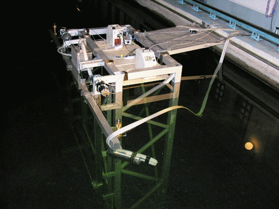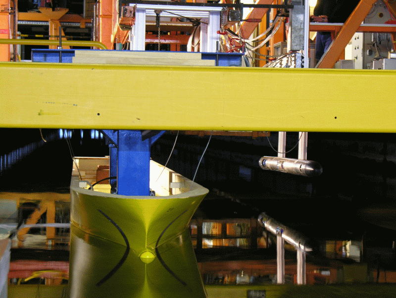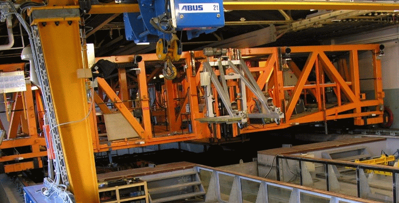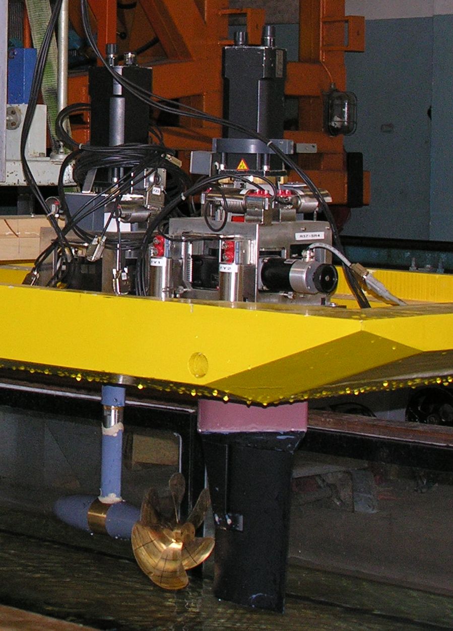
For the measurement of forces and moments on bodies within flows, 3 component and 6-component balances are available with different measurement ranges and areas of operation. The balances R37SR1 … 6 are suitable for open water tests and for use in models. The devices are designed for measurement of rudder and fin forces and to capture integral forces on thrusters. The majority of balances are equipped with a rotary table, which can be set with the angle statically and dynamically. For use with thrusters the balances are equipped with a drive motor. The total torque is detected by a torque sensor.
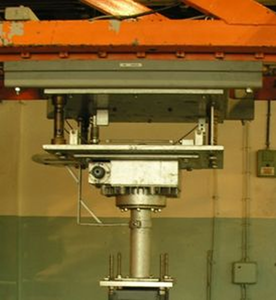
The balance R200 is designed for open water tests with large motors and for general force measurements. It is additionally equipped with a turntable, drive motor and torque sensor.
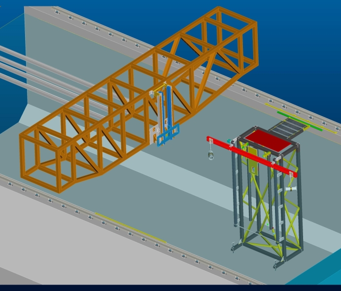
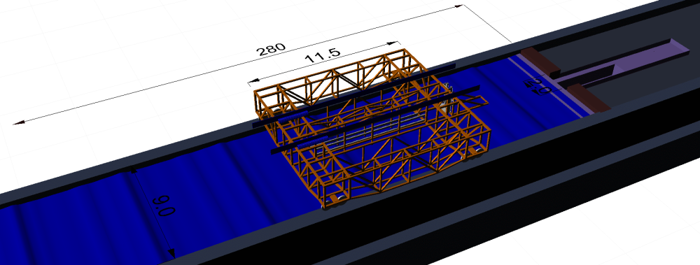
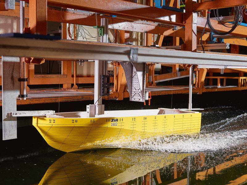
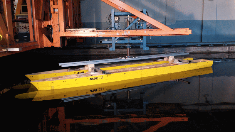
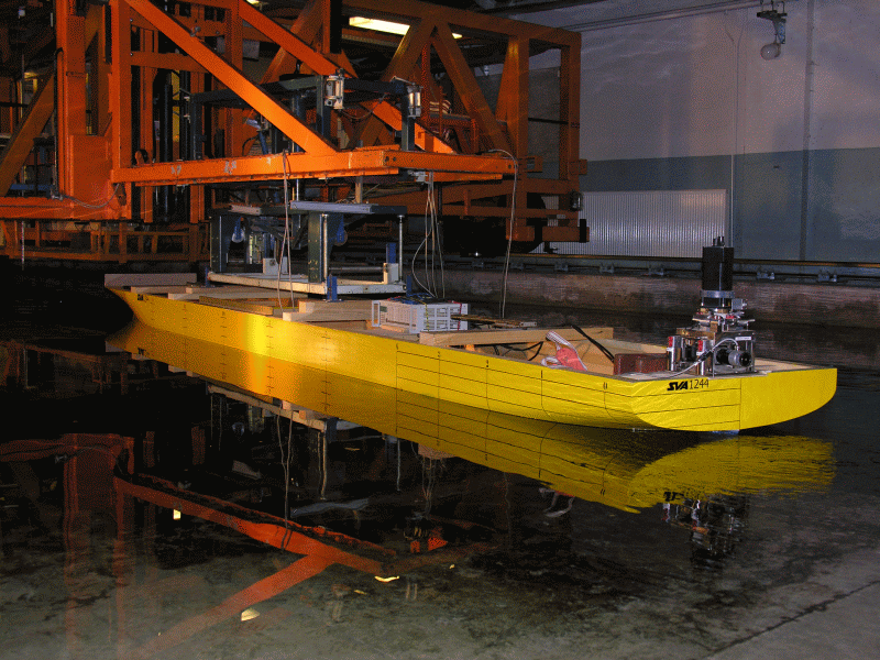
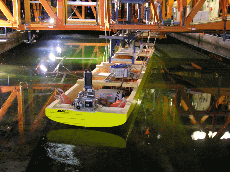
The balances R100, R 250 and R 350 can be used for force measurements on ships and floating or submerged structures. These allow the change in yaw, trim and angle of heel, and the application of different connections.

Technical Specifications Multicomponent Balances |
||||||||
| Main Parameters | R37SR 1, 2 | R37SR 3, 4 | R37SR 5, 6 | R200 | R100 | R250 | R300 | |
| Components | 3 | 6 | 3 | 6 | 3 | 6 | 3 | |
| Forces | Fmax [N] | 500 | 500 | 1000 | 2000 | 1000 | 2500 | 3500 |
| Torque | Qmax [Nm] | 20 | 20 | 20 | 20 | — | — | — |