Author: pa

Sea Trial Evaluation

Prior to delivery and acceptance of new ships, the achievable speed for a given power and the power consumption for a given speed is determined in a trial (measured mile) with the full-scale version. Primarily, it is checked as to whether the contractual parameters have been achieved and, secondarily, whether the required EEDI is fulfilled.

To determine the delivered power, the torque and rotational velocity of the propeller for a given speed can be measured. This measurement can be carried out by the SVA onboard the ship with own measurement equipment.

Unlike model tests, the conditions in a measured mile are only in the rarest cases ideal. It can hardly be avoided that measured miles must be carried out in wind and waves, with shallow water effects, in areas of current, etc. To convert the environmental influences on the contract or experimental conditions, the measured mile results must be evaluated. The SVA Potsdam offers such calculations which are performed in accordance to the current standards of IMO and ITTC.


Power Measurement at Full-Scale

Leistungsmessung_1_small

Performance measurements on the propeller shaft are performed during measured miles, acceptance of new ships and, in case of problems, in the area of propeller/engine tuning to determine the power consumption of the propeller at full-scale. For this, the torque and speed of the propeller shaft or gear coupling shafts and intermediate shafts are measured. The torque measurement is carried out with strain gauges and the speed measurement with a magnet-hall sensor system. With a Bluetooth measurement module, the signals are processed and transmitted digitally to a measuring computer. Additional metrics like speed, heading, rudder angle and trim of the vessel may be time equidistantly recorded. For this purpose, GPS / DGPS systems, gyroscopes and other instrumentation are available.

Manoeuvering

man_CFD_schraeg

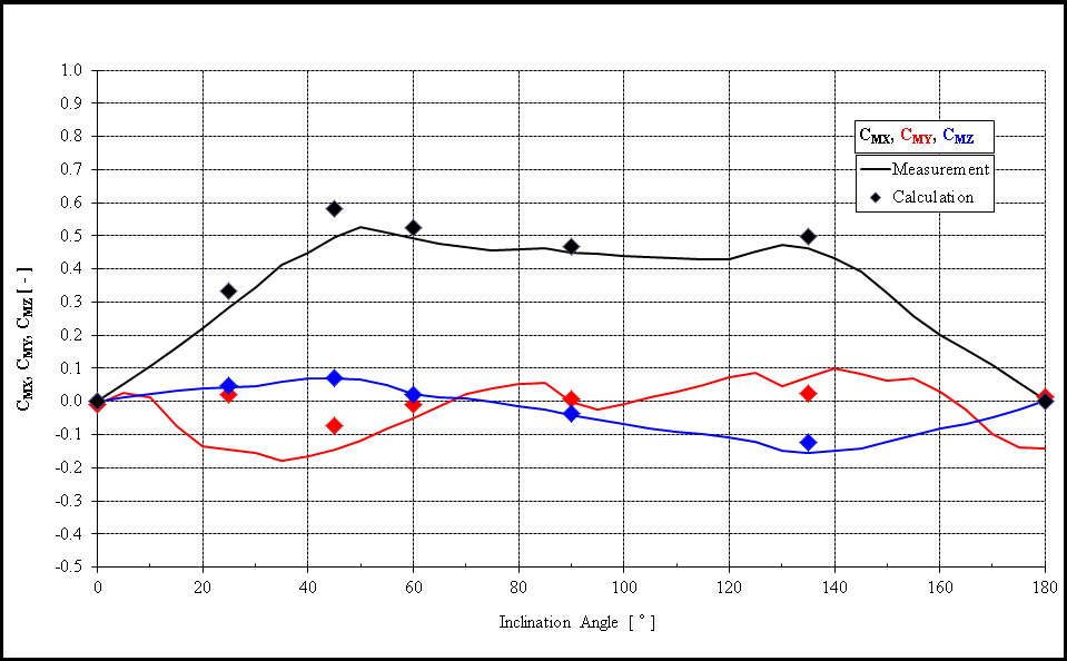
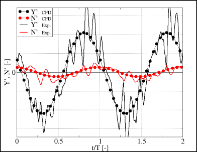
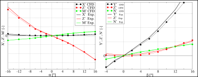
The use of numerical calculation methods offers many possibilities to investigate ship manoeuvres. In general, numerical calculations analogous to PMM-experiments (Planar Motion Mechanism) are carried out in which static and dynamic simulations are performed to determine the forces and moments as a function of a specific movement of the ship. From this, the hydrodynamic coefficients can be derived and fed into a mathematical model. With the calculation of a complete set of hydrodynamic coefficients, any manoeuvre can be simulated. To verify the quality of the numerical calculations, the calculation results are continually validated with the corresponding measured values.

Numerical simulations allow to:

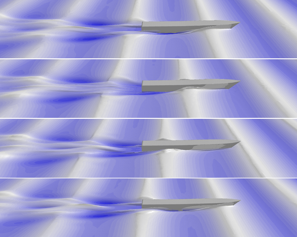
  • Simulate manoeuvring behaviour in model and full-scale
  • Simulation of static and dynamic tests
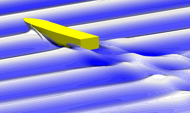
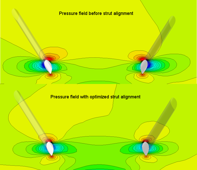
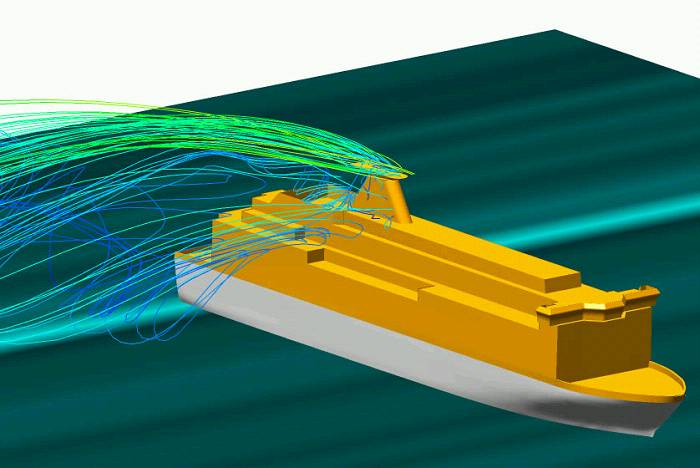
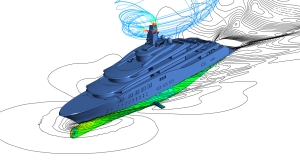
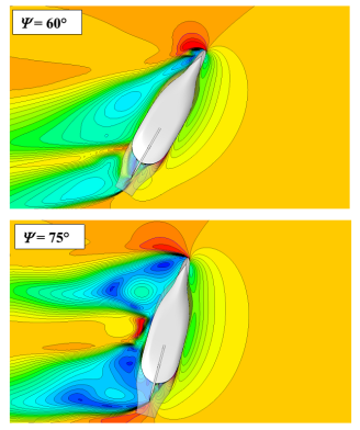
  • Visualisation of flow, detection of separating flow
  • Design of control elements such as rudders, thrusters, etc.

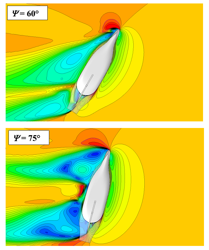
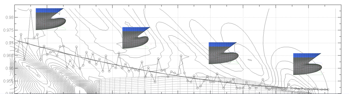
The rudder is by far the most frequently used control element; it operates in the wash of the propeller. Below, the pressure distribution on the rudder for a rudder angle of δR = 20° with a rotating propeller is shown.


CFD_man_abb2_m_RahmenCFD_man_diag_m_Rahmen


Context Related References / Research Projects

[1] Lübke, L.: Investigation of a Semi-Balanced Rudder, 10th Numerical Towing Tank Symposium, Hamburg, 24.09.2007
[2] Lübke, L.: Investigation of a Semi-Balanced Rudder, 14. SVA Forum, Potsdam, 07.11.2007
[3] Lübke, L.: Investigation of a Semi-Balanced Rudder, ANSYS Conference & 25th CADFEM Users Meeting 2007, Dresden, 21. – 23.11.2007
[4] Lübke, L.: Numerische und experimentelle Untersuchungen an einem Halbschweberuder, STG-Sprechtag, Verbesserung der Propulsions- und Manövriereigenschaften von Schiffen, Papenburg, 18.09.2008
[5] Lübke, L.: Numerische PMM-Tests für Unterwasserfahrzeuge, ANSYS Seminar, Simulationswerkzeuge für die Marine und Offshore Industrie, Hamburg, 05.11.2008
[6] El Moctar, O., Brehm, A., Lübke, L.: Hydrodynamische und strukturmechanische Untersuchung von Rudern großer, schneller Schiffe (XXL-Ruder), PTJ Statustagung, Warnemünde, 11.12.2008
[7] Lübke, L.: Numerische und experimentelle Untersuchungen der effektiven Ruderzuströmung beim Manövrieren, 2. SVA Forschungsforum „Theoria cum praxi“, Potsdam, 29.01.2009
[8] Lübke, L.: Manoeuvering Simulations of Underwater Vehicles, 12th Numerical Towing Tank Symposium, Cortona Italy, 04.-06.10.2009
[9] Lübke, L.: Investigation of a Semi-balanced Rudder, Ship Technology Research, Vol. 56, No. 2, 2009

Seakeeping

CFD_seegang_abb1_small

seegang_CFD_schnellboot_small

The use of numerical methods offers many opportunities to examine ships at sea. The SVA can use the program system UTHLANDE or RANSE Method depending on the application. UTHLANDE provides the ability to perform seaway calculations based on linear and non-linear strip method. Using this method, monohulls and catamarans can be studied over a wide range of applications and short- and long-term statistics can be calculated. For special cases or the simulation of non-linear applications, RANSE Method (ANSYS Fluent) is used.

With numerical calculations, issues can be examined in terms of added resistance or the acceleration and motion behavior of ships. Added resistance at sea is an essential aspect in order to determine power requirements and operating costs of vessels correctly. The motion behaviour at sea, however, is an essential aspect of comfort and determines the operating limits of ships.

The numerical seaway simulations with RANSE procedures include the following applications:

  • Seaway from any direction, stationary and in motion
  • Calculation of regular and irregular sea states, with the focus on the calculation of regular seaway
  • Determination of the added resistance
  • Determination of accelerations


Energy Saving Devices

Lorem ipsum dolor sit amet, consectetur adipiscing elit. Curabitur lectus elit, porttitor quis placerat eget, porttitor eget nunc. Aliquam vel ex lectus. Sed ultricies sed nisi vitae faucibus. Integer sit amet dapibus dolor. Proin tincidunt orci a neque convallis tincidunt. Sed consectetur vel ex sit amet euismod. Praesent commodo ex id ligula porttitor semper. Morbi tempus justo id nisl mattis, eu laoreet sapien suscipit. Aenean est lacus, sodales nec varius vel, convallis sit amet nisl. Cras eleifend, ante vel tempus aliquam, tellus orci tristique nisl, nec convallis diam metus at diam. Proin egestas mauris ligula, in elementum ex efficitur eget. Praesent viverra commodo lacus, eget molestie dui molestie sed. Aliquam nec mollis quam. Phasellus euismod consectetur tincidunt. Phasellus sit amet felis elementum, bibendum dolor quis, blandit magna.

Curabitur eu massa vitae turpis laoreet molestie in eu velit. Nunc in condimentum nisl. Suspendisse potenti. Nullam ante ex, varius nec dignissim faucibus, suscipit vel eros. Aliquam condimentum nisi sit amet est vestibulum tincidunt. Quisque nisl enim, tempor in porttitor sed, ornare ac massa. Mauris sed convallis nisl. Aenean volutpat finibus turpis. Ut porta sagittis ligula congue vestibulum.

Hull Optimization

Wellenbock_opti
An initial ship design is rarely optimal in terms of its hydrodynamic efficiency. Often, a new design is derived from geometries of existing ships and “manually” adjusted for the new mission profile. To maximise the economic, environmental, and in particular, fuel efficient operation, the vessel geometry can be optimised without effecting other design criteria such as displacement distribution, load capacity, speed, stability, wake distribution, etc. This optimisation is performed with the use of CFD methods, either by means of a mathematically based, automatic optimisation, or knowledge based on the groundwork of decades of experience of engineers.
For this optimisation, among other things, various parametric models of the “CAESES” software are used. The optimisation is done on the basis of viscous CFD calculations, since these are considerably more reliable in optimising than the potential theory method. The savings benefits are generally considerable and give, over the life of the vessel, a significant increase of the “return on investment”. Classical optimisation tasks are the optimisation of bows, bulbous bows, and sterns. While on new designs an optimal concept is at once available, in the area of retrofitting, especially a bulbous bow, optimisation makes sense. Generally, this is done for the customer’s predefined mission profile fully parametrically. The example shows the development of the drag resistance of a ship geometry depending on the variation of the bulbous bow.
As a secondary condition of minimum resistance or propeller thrust, optimisation of the flow into a propeller (homogeneity of the wake) can be considered.

Propeller struts, stabiliser fins and other appendages can make a significant contribution to the ship’s resistance. Through the optimised shape and alignment of the appendages, the resistance and the loading of the attachments are minimised. Accordingly the propeller wash becomes homogeneous, improving the quality and efficiency of propulsion and contributing to the reduction of vibration and noise.

messe_ohne_Schrift


Context Related References / Research Projects

[1] Lübke, L.: Optimierung von Schiffsanhängen an großen Yachten, Fachseminar Numerische Simulation und Optimierung, Berlin, 24.05.2007
[2] Lübke, L.: Formoptimierung unter Berücksichtigung der Charakteristik des Nachstromfeldes, Forschungsthema, 04/2007 – 12/2009
[3] Lübke, L.: CFD in Ship Design, STG Sprechtag, 25.09.09 Hamburg
[4] Lübke, L.: CFD in Ship Design, ANSYS Conference & 32nd CADFEM Users Meeting 2014, Nürnberg, June 4-6, 2014