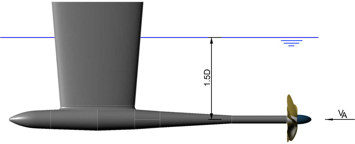
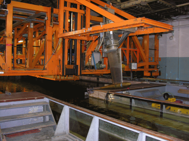
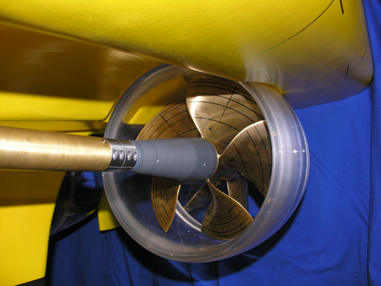
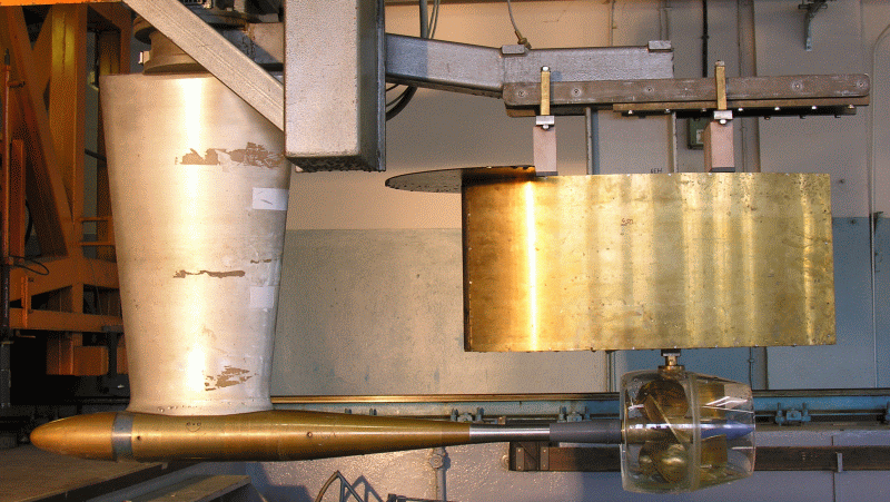
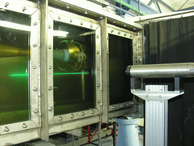
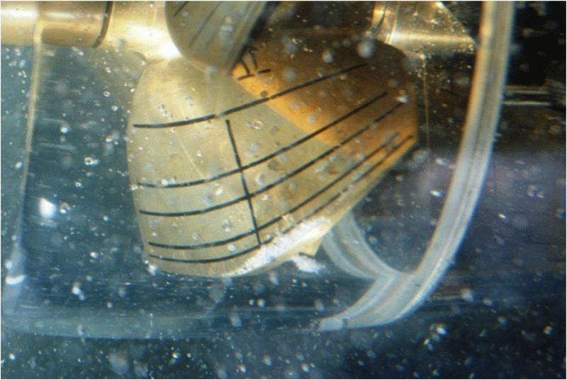
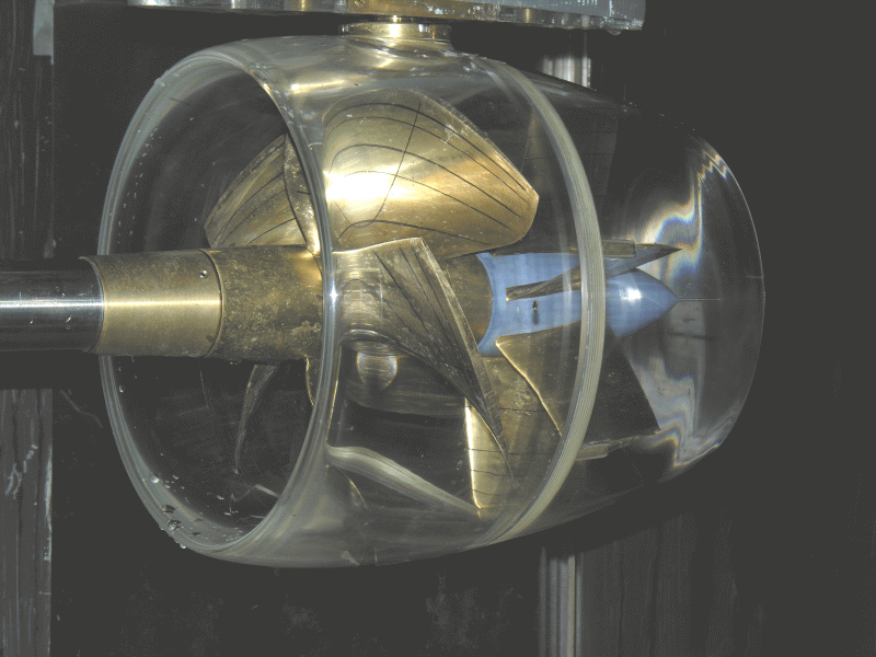
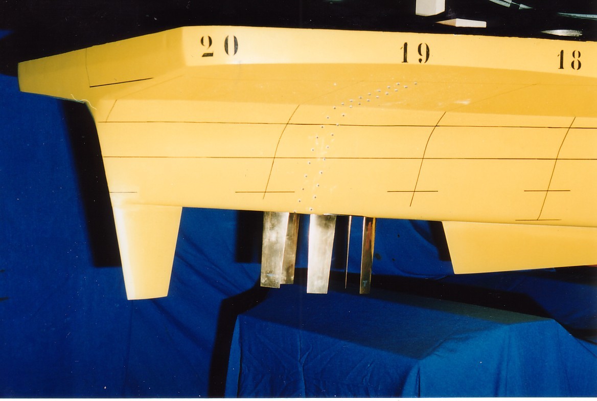
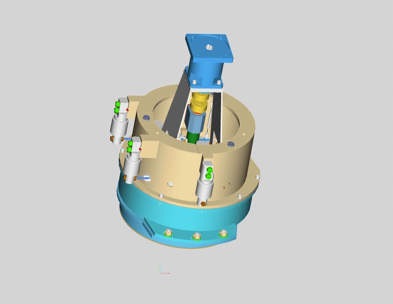
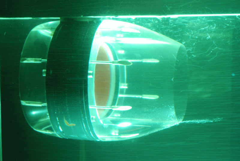
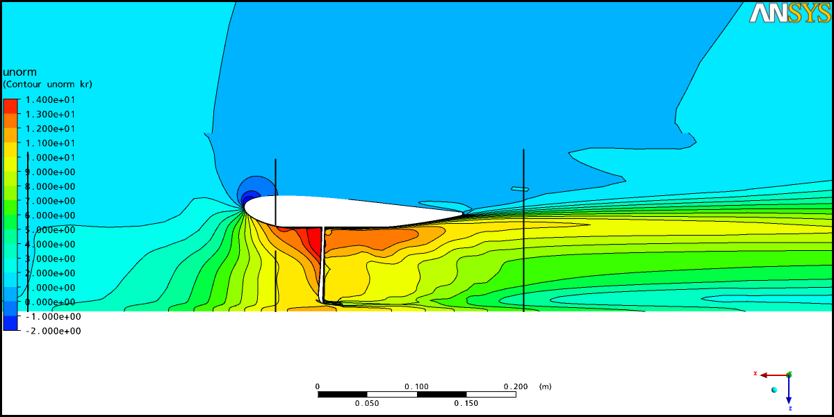
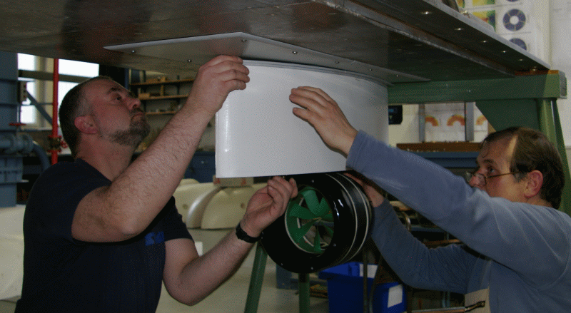
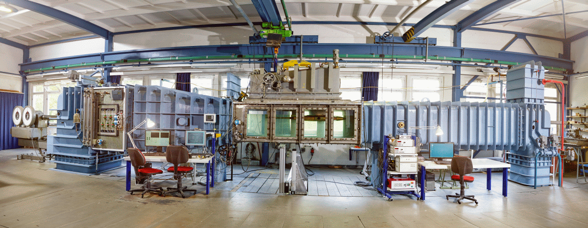
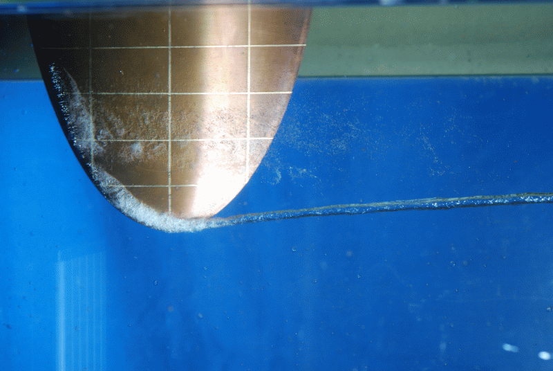
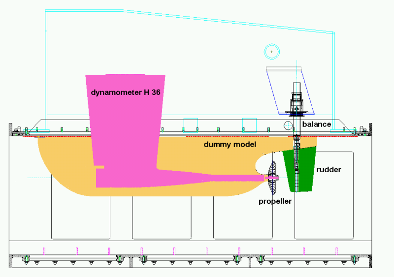
Author: pa

Linearjet

Lorem ipsum dolor sit amet, consectetur adipiscing elit. Curabitur lectus elit, porttitor quis placerat eget, porttitor eget nunc. Aliquam vel ex lectus. Sed ultricies sed nisi vitae faucibus. Integer sit amet dapibus dolor. Proin tincidunt orci a neque convallis tincidunt. Sed consectetur vel ex sit amet euismod. Praesent commodo ex id ligula porttitor semper. Morbi tempus justo id nisl mattis, eu laoreet sapien suscipit. Aenean est lacus, sodales nec varius vel, convallis sit amet nisl. Cras eleifend, ante vel tempus aliquam, tellus orci tristique nisl, nec convallis diam metus at diam. Proin egestas mauris ligula, in elementum ex efficitur eget. Praesent viverra commodo lacus, eget molestie dui molestie sed. Aliquam nec mollis quam. Phasellus euismod consectetur tincidunt. Phasellus sit amet felis elementum, bibendum dolor quis, blandit magna.

Curabitur eu massa vitae turpis laoreet molestie in eu velit. Nunc in condimentum nisl. Suspendisse potenti. Nullam ante ex, varius nec dignissim faucibus, suscipit vel eros. Aliquam condimentum nisi sit amet est vestibulum tincidunt. Quisque nisl enim, tempor in porttitor sed, ornare ac massa. Mauris sed convallis nisl. Aenean volutpat finibus turpis. Ut porta sagittis ligula congue vestibulum.

Vertical Axis Rotors

VSP_am_Modell_SeiteVSP_Antrieb_CAD_small

Vertical axis rotors like the Voith Schneider Propeller (VSP) are special propulsion systems that give ships very good maneouvrability with very short control times. These systems are therefore often installed on double-ended ferries and special purpose vessels. In the SVA many ships with VSP’s were examined, such as tugboats, double-ended ferries with 2 and 4 VSP’s, and offshore supply ships. To get a deeper insight into the mechanism of action of Voith Schneider Propellers, several research projects were conducted [1], [2] in the SVA Potsdam. Among other things, the interaction of VSP and hull on double-enders [3], [4] was investigated. Here, a special SVA measuring balance was developed which in comparison to the standard methods, enables the measurement of the thrust in the model test and thus to determine the interaction parameters in propulsions tests. The interaction parameters can provide information on optimisation potentials.

In the project “Offshore Support Vessels with Voith Schneider Propellers” basic investigations were performed for the propulsion of OSV’s with VSP’s [6]. The focus was again on the interaction between VSP and hull. Simultaneously, the current methods of evaluation have been reviewed.

For model testing, VSP models are provided by the Voith company. For normal power and speed prediction, the thrust measurement on VSP’s is not absolutely necessary. However, the additional amount of preparation and testing time lends itself to optimisation questions.


Context Related References / Research Projects

[1] Heinke, H.-J.: Model tests with Voith Schneider Propellers at high thrust coefficients, Hydrodynamic Symposium – Voith Schneider Propulsion, Heidenheim, März 2006
[2] Heinke, H.-J.: High-Speed Camera Observations of the Cavitation at a Voith Schneider Propeller, 2nd Symposium Voith Schneider Technology, Heidenheim, June 2008
[2] Jürgens, D.; Grabert, R.: New Hydrodynamic Aspects of Double Ended Ferries with Voith-Schneider Propeller, 2nd International Conference on Double Ended Ferries, Alesund, Norway, 2003
[4] Grabert, R.: New Insight into the Hydrodynamics of Double-Ended Ferries with Voith Schneider Propellers, 3rd Hydrodynamic Symposium on Voith Schneider Propulsion, Constance, 16 – 18 June 2010
[5] Grabert, R.: Analysis of the Interaction VSP – Hull of Modern OSV, 4th Hydrodynamic Symposium on Voith Schneider Propulsion, Heidenheim, 12 – 14 June 2012
[6] Heinke, C.: Investigations of OSV with VSP Propulsors at SVA Potsdam, 5th Hydrodynamic Symposium on Voith Schneider Propulsion , Heidenheim, 30.9. – 2.10. 2014

Inline Thruster

ILT_rot_small

An inline thruster is an electric ring motor with a rotor and nozzle combined in a powerful propulsion system without shaft and gearbox. Four inline thrusters with a rotor diameter of 170 mm have been developed in the SVA for model tests. The models are studied in open water and cavitation tests. In addition, velocity measurements, dynamic flow monitoring and open water experiments at different azimuth angles and in off-design conditions were carried out for various industrial applications.

The forces and moments on the different elements of the inline thrusters were calculated in the model and at full-scale. The results of these calculations were the basis for the investigation of the Reynolds number effects and for the optimisation of the rotor and nozzle geometry.
Propulsion and maneuvering tests showed the applicability of inline thrusters for main propulsion system of ships [1], [2].


ILT_am_Grachtenboot_DetailILT_an_M1263_1_heck_smallILT_an_M1263_2_bb_stb_smallILT_im_KT_small

ILT_CFD_unorm_130_m_RahmenILT_Einbau_small


Context Related References / Research Projects

[1] Heinke, C.: Flachwassergeeignete Propulsionssysteme mit hoher Effizienz, SVA-Bericht 3502, FuE-Abschlussbericht, Potsdam, November 2008
[2] Heinke, H.-J.: Inline Thruster als Hauptantriebssystem, SVA-Bericht 3670, FuE-Abschlussbericht, Potsdam, Mai 2010

Transverse Thruster

Bild1_Prinzipskizze QRABild2_Querkanal_QRA

Thrusters of various designs are used to improve manoeuverability. The variations go from impeller, z-drives and retractable types to permanently installed channel thrusters. For the design of bow thrusters, details are needed on the basic parameters of the propeller and interaction with the channel in particular. For bow thrusters with propellers, different approximation methods were derived. At SVA, the method of Bladt and Wagner [3] is used for the design of thrusters. Investigations with thrusters can similarly be carried out as ducted propellers up to a certain size (relation of propeller diameter to length of the tunnel). The following figure shows a schematic diagram of the experimental setup.

For cavitation tests with propellers for thrusters, the cross-channel system 25A26 was developed [2].

The propeller is driven with the J25 dynamometer. The channel inner diameter is 209 mm. At the end of the channel a nozzle-like constriction is arranged. This nozzle causes a throttling effect that achieves high thrust loads of the propeller in the experiments without a working impeller. Smaller loads can be realised by increasing the velocity in the pipe by a working impeller. The velocity in the channel is determined by pressure measurements. The velocity measuring device is calibrated by the measurement of the velocity distribution in the jet of the outlet of the nozzle. Therefor the LDV-measuring device is used in the cavitation tunnel. The calibration is performed with and without propellers. The static pressure which is required for calculating the cavitation number is measured in the entrance of the channel. The entrance of the cross channel can be equipped with a vertical or inclined plate relative to the channel axis.


Context Related References / Research Projects

[1] Vollheim, R.: Modellversuche zur Entwicklung eines Bugstrahlruders Schiffbauforschung 18 1/2/1979
[2] Schröder, G.: Eine Einrichtung für Modellversuche an Propellern für Querstrahlruder Schiffbauforschung 23 3, 1984
[3] Bladt, K.-J.: Beitrag zur Auslegung von Querschubanlagen mit Propeller für Schiffe, www.jbladt.drupalgardens.com, 2013

Podded Drives

SSPCFK Propeller Pod in Cavitation Tunnel

The main feature of podded drives is the integration of a powerful electric drive in a hydrodynamically optimised pod beneath the ship which drives the propeller directly. The full power can be used in any azimuth direction (0 – 360).
The podded drive is a propulsion system comprised of the components propellers and pod housing. The development and optimisation of podded drives requires knowledge of the interaction between propeller and pod housing and about the influence of design parameters on the characteristics of the system.
SVA Potsdam has been working in the field of podded drives since 1995 [1], [2]. Among other studies, the applicability of podded drives, dynamic flow calculations, analyses of various podded drives as well as numerous model studies have been performed there [3], [4], [8]. Developments for podded drives were conducted in collaboration with various manufacturers [3], [9].
As part of a BMWi funded project “Integrated Ship Design for Ships with Podded Propulsion Systems”, aspects of ship design for ships with podded drives were examined. In the BMWi funded project “High-Speed Pod”, concepts for podded drives with application speeds up to 30 knots were developed and studied experimentally and computationally [5], [6]. The ideas and findings resulting from these projects were the basis for the development of High Efficiency Pods with HTS technology [9].
The manoeuvrability of propulsion systems with podded drives were examined as part of a BMBF funded project [7]. The arrangement of the pod at the stern of the ship, the use of fins, and the influence of the propeller assembly were analysed experimentally and computationally.
Standard podded drives with pull and push propeller variants have been developed and investigated experimentally [6], [8], [9]. The pod housings (gondolas) were particularly varied with regard to the gondola diameter and the transition from the propeller to the gondola in order to determine the influence of geometric parameters on the characteristics of podded drives (open water, propulsion, cavitation).
The development and the study of podded drives places high demands on measurement technology and experimental methods. For open water, propulsion and cavitation measurements, manoeuvring and speed measurement systems on podded drives have been developed, tested and used successfully. To validate the evaluation and forecasting methods for measurements with podded drives, CFD calculations were performed.
With the available azimuth measuring systems for podded drives, pull, push, twin, and counter-rotating propeller assemblies can be analysed. Among other things, the thrusts and moments of the propeller are measured in the shaft and the lateral and vertical forces can be measured at the housing.

Pods_Galerie_KT_HSP_im_ Kavitationsversuch

Pods_Modell_mit_Pods_small

Pods_u_p_HTS1A_VP1357

Pods_u_p_HTS1C_VP1357


Context Related References / Research Projects

[1]    Heinke, H.-J.: Azimuthing propulsion – Experiences of SVA, 6th SVA-Forum “Azimuthing Propulsion – new challenges and chances”, Potsdam, 29th April 1998
[2]    Abdel-Maksoud, M., Heinke, H.-J.: Investigation of Viscous Flow Around Modern Propulsion Systems, CFD ’99, The International CFD Conference, 5-7 June 1999, Ulsteinvik
[3]    Kaul, S., Heinke, H.-J.; Abdel-Maksoud, M.: Hydrodynamische Optimierung von Podded Drives und aktuelle Anwendungen in der Großausführung, 54. Sitzung des FA „Schiffshydrodynamik“ der STG, Hamburg, September 2000
[4]    Heinke, H.-J.: Kavitationsuntersuchungen zu Podded Drives, 20. Strömungstechnische Tagung des Instituts für Strömungsmechanik der TU Dresden, 6. Oktober 2000
[5]    Heinke, H.-J.: Alternative Propulsion Concepts for Fast Navy Ships, Part II: Podded drives for navy ships,  International Lecture Day “Unconventional Hull Forms for Naval Vessels”, Potsdam, September 2001
[6]    Heinke, C., Heinke, H.-J.: Investigations about the Use of Podded Drives for Fast Ships, FAST 2003, Ischia (Italy), Oct. 2003
[7]    Steinwand, M.: Manoeuvrability of a Single Screw Ship with Pod, Hydronav’2003, Gdansk, Poland, Oct. 2003
[8]    Heinke, H.-J.: Investigations about the forces and moments at podded drives, First International Conference on Technological Advances in Podded Propulsion, Newcastle, UK, April 2004
[9]    Heinke, H.-J.: Hydrodynamische Untersuchungen für einen Podded Drive mit HTS-Synchronmaschine, Statustagung Schifffahrt und Meerestechnik, Bundesministerium für Wirtschaft und Technologie, 3. Dezember 2009, Rostock-WaPartner

Thruster

Thruster_Schottel_RuderpropThruster_Schottel_Ruderprop_CFD

Thrusters are propulsion systems used for ships and platforms where manoeuvrability is an important criterion. Thrusters can usually swivel 360° so that the system can act in any direction. The propeller works in front of or behind the housing (pull and push) which results in strong interactions between the propeller and the housing. Experimental and numerical investigations of thrusters are conducted because of these interactions and also special operating conditions such as bollard pull, manoeuvring, off-design, which are more demanding than conventional propellers. When analysing thrusters mostly open water propulsion and cavitation tests are carried out.

Special propulsion and measuring systems have been developed for the study of thrusters. The SVA owns propulsion and measuring systems for use in the towing tank and cavitation tunnel for testing thrusters with pushing or pulling propellers, twin and also contra rotating propellers. The systems allow the measurement of thrusts and moments of the propellers and the determination of housing resistance. The system forces and torques of the thruster are measured with 3- or 6-component balances.

Tests and calculations for thrusters are carried out in particular for propeller manufacturers (determination of the characteristics of thrusters, optimisation and development), shipyards and shipping companies (Propulsion). To convert the model test results to full-scale, the SVA has developed its own method for Reynolds number correction for thrusters. Systematic CFD calculations of thrusters were carried out in the R & D project “Correlation of Z-Drives with Ducted Propellers” [2], [4].

In recent years, aspects of DPability of thrusters were increasingly analysed. As part of the research project “Thruster for Dynamic Positioning” [5], [6] extensive studies on the influence of gondola and nozzle angle on the operating parameters of the thruster, the interaction of the thruster with the platform, and the mutual interaction of the thrusters were performed.

For the study of DP capability of platforms, special propulsion and measuring systems have been developed to ensure the variability of the inclination of the gondola housing and an unlimited pivoting of the thruster.

Thruster_CFD_PlatformThruster_Offshore_PlatformThruster_Offshore_Platform_in_SR


Context Related References / Research Themes

[1] Abdel-Maksoud, M., Heinke, H.-J.: Investigation of Viscous Flow around Modern Propulsion Systems, CFD’99, Ulsteinvik, Norway, June 1999
[2] Abdel-Maksoud, M., Heinke, H.-J.: Scale Effects on Ducted Propellers, 24th Symposium on Naval Hydrodynamics, Fukuoka, Japan, July 2002
[3] Heinke, H.-J.: Azimuthing propulsion – Experiences of SVA, 6. SVA – Forum „Azimuthing Propulsion – new challenges and chances“, Potsdam, April 1998, Schiffbauforschung 38 (1999) 1
[4] Heinke, H.-J., Abdel-Maksoud, M., Pierzynski, M. (2006): Korrelation Z-Antrieb mit Düsenpropeller, Schiff & Hafen, 2006, Heft 5
[5] Heinke, H.-J.: Model Tests with the Voith Radial Propeller, 3rd Hydrodynamic Symposium on Voith Schneider Propulsion, Heidenheim, June 2010
[6] Heinke, C.: Erhöhung der DP-Fähigkeit durch optimalen Einsatz von Thrustern, STG-Hauptversammlung, Hamburg, November 2012, Jahrbuch der Schiffbautechnischen Gesellschaft, 107. Band, 2012