Propulsion @en

Hydroacoustics

Hydroakustik_Foto4_small

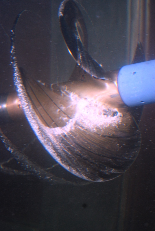
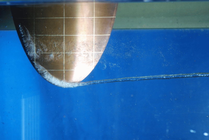
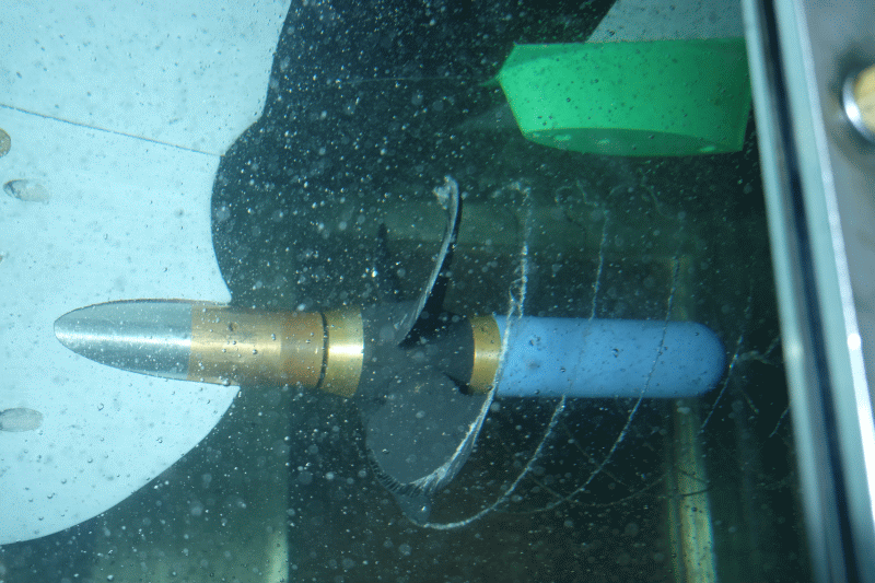
The main cause of man-made noise emissions in the sea is currently the propeller. Studies of propeller induced noises are carried out in the form of hydroacoustics, structure-borne noise and pressure pulse measurements, both in model testing as well as for full-scale [1].

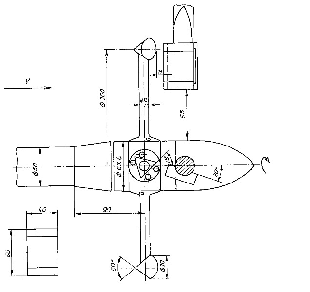
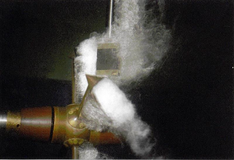
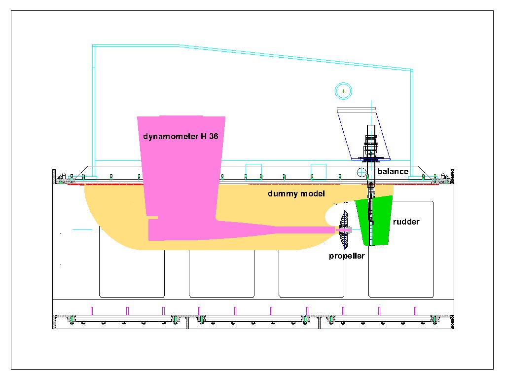
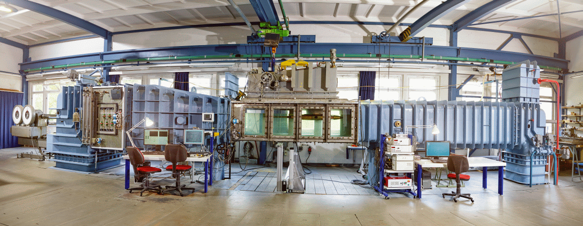
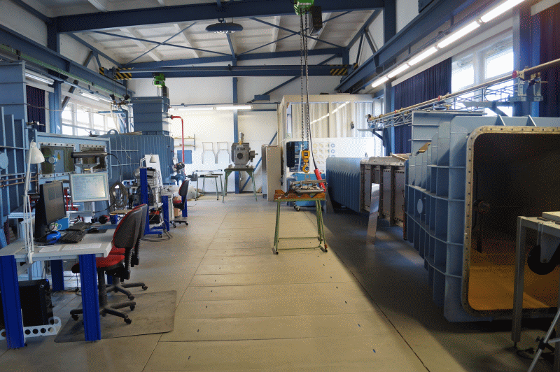
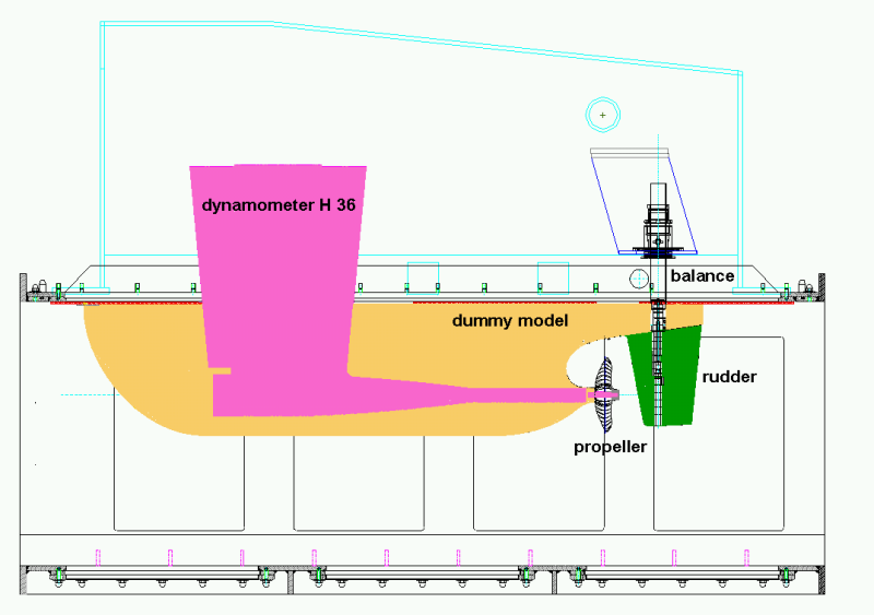
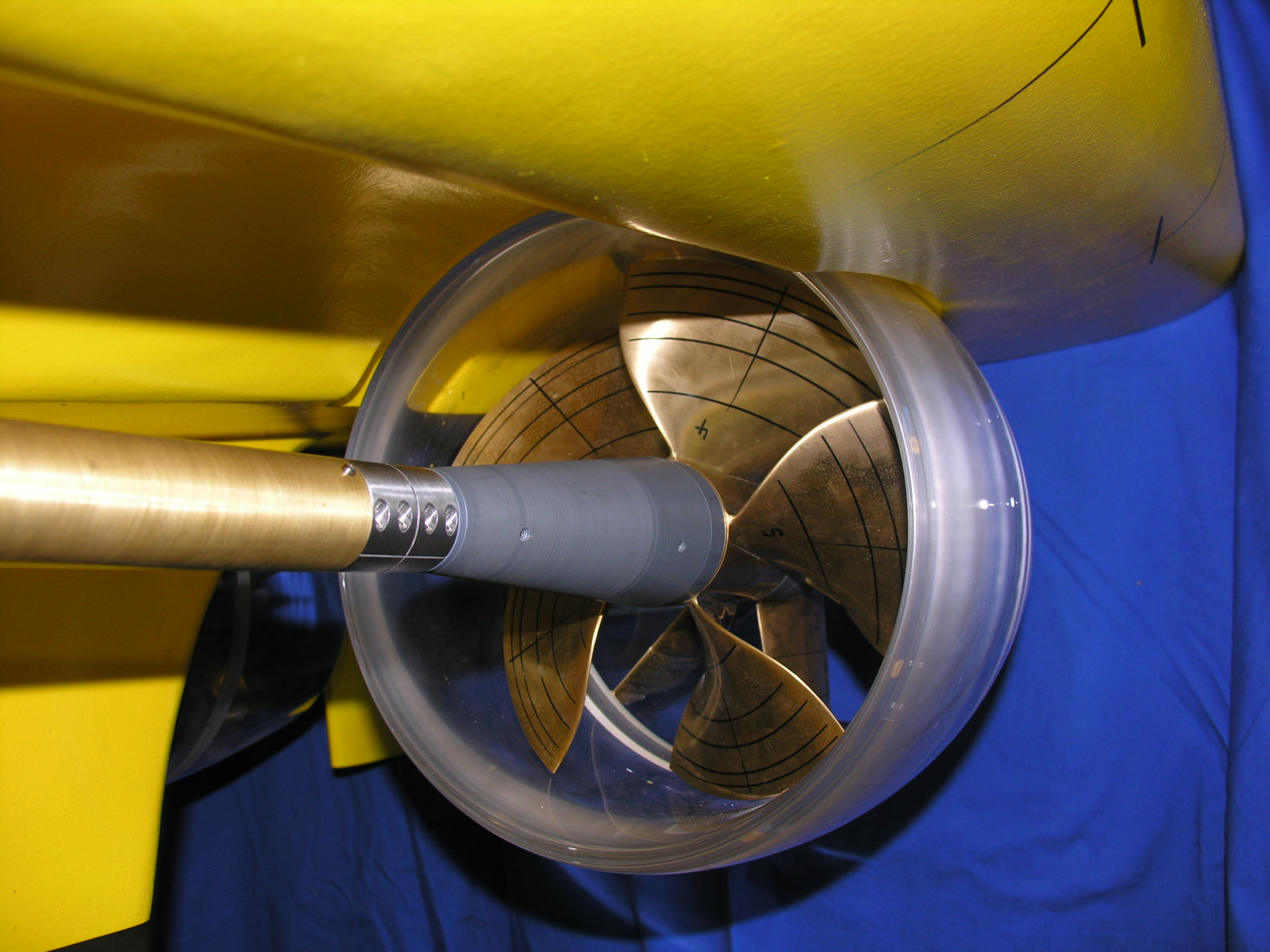
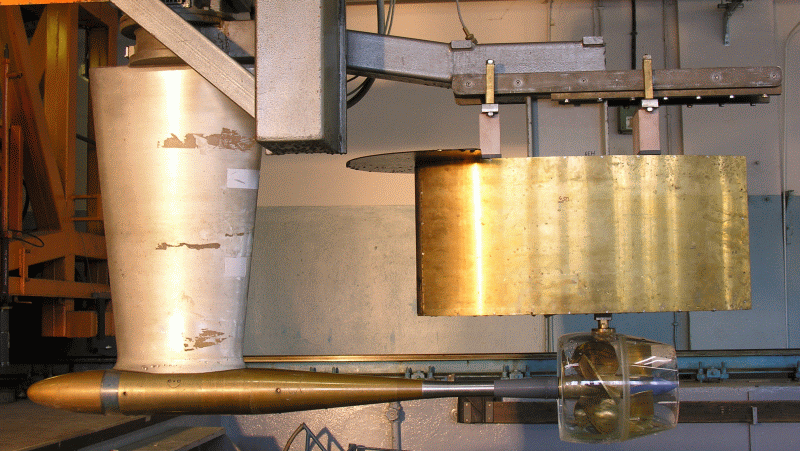
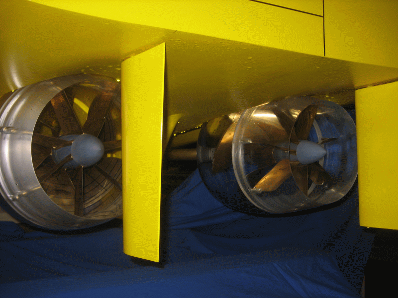
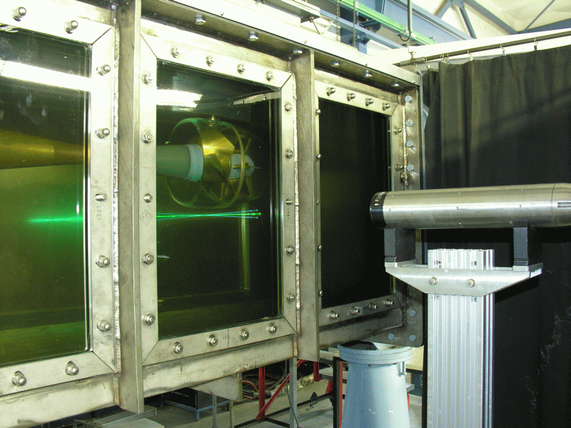
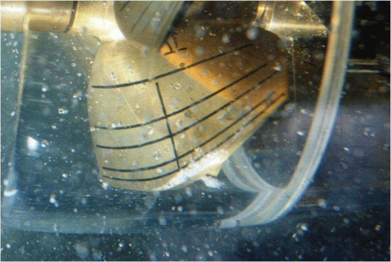
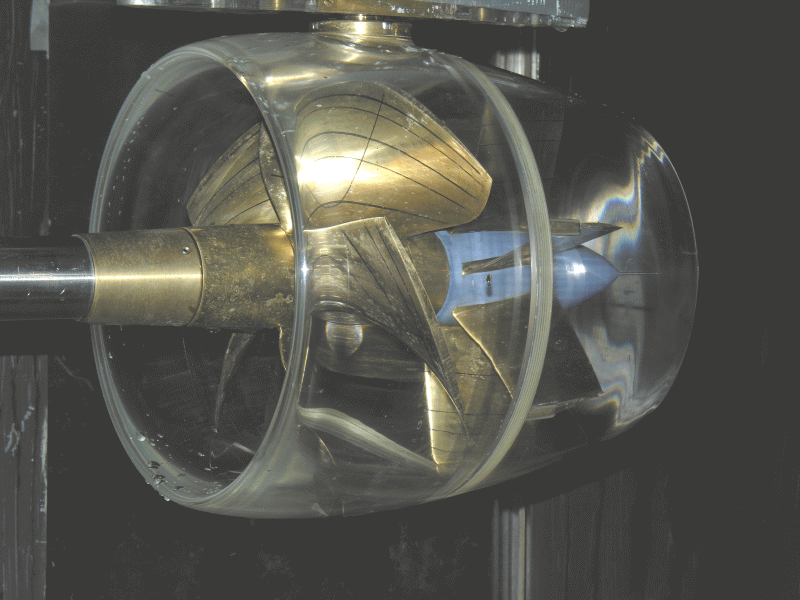
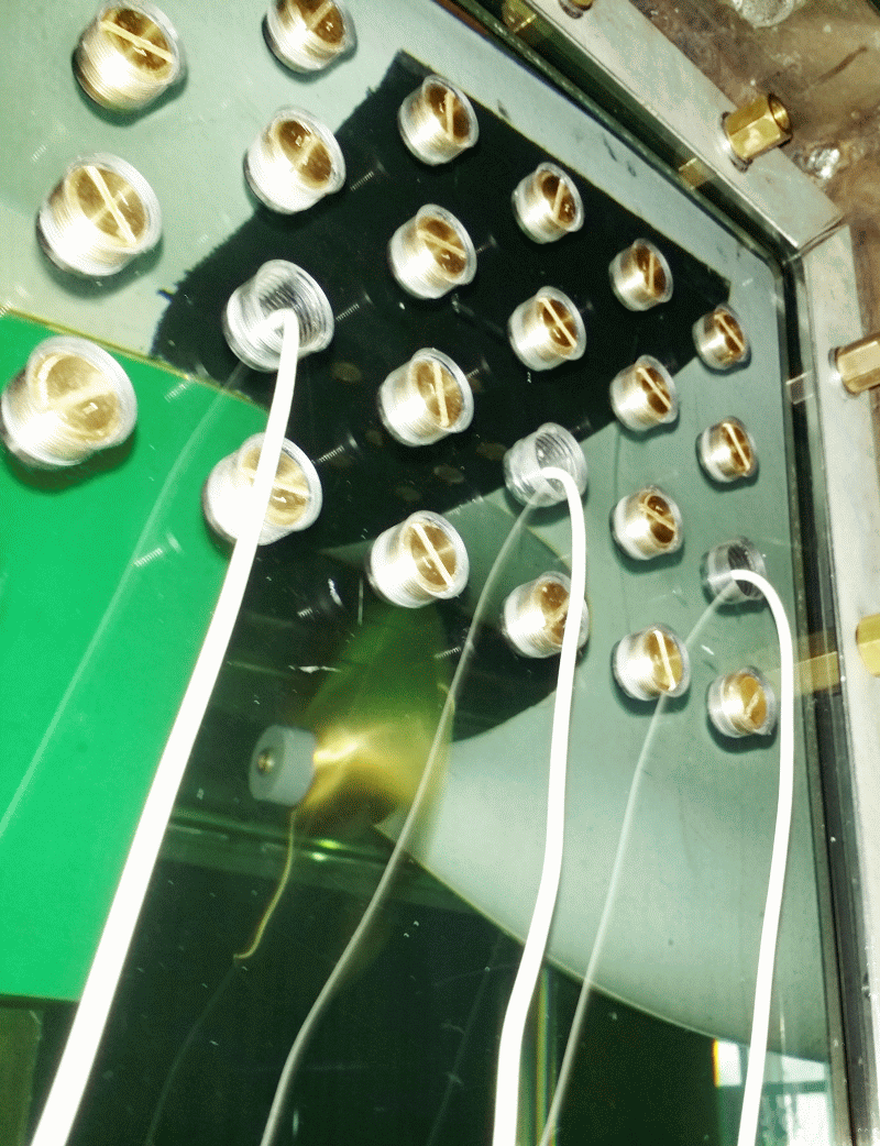
The model measurements for determining cavitation noise are performed in the cavitation tunnel. Here hydrophones (on a dummy model or decoupled flow water tank), accelerometers and pressure sensors are used which cover the widest possible frequency range. The measurements and the subsequent scaling of the noise to the full-scale are carried out according to the format recommended by ITTC [2], [3].

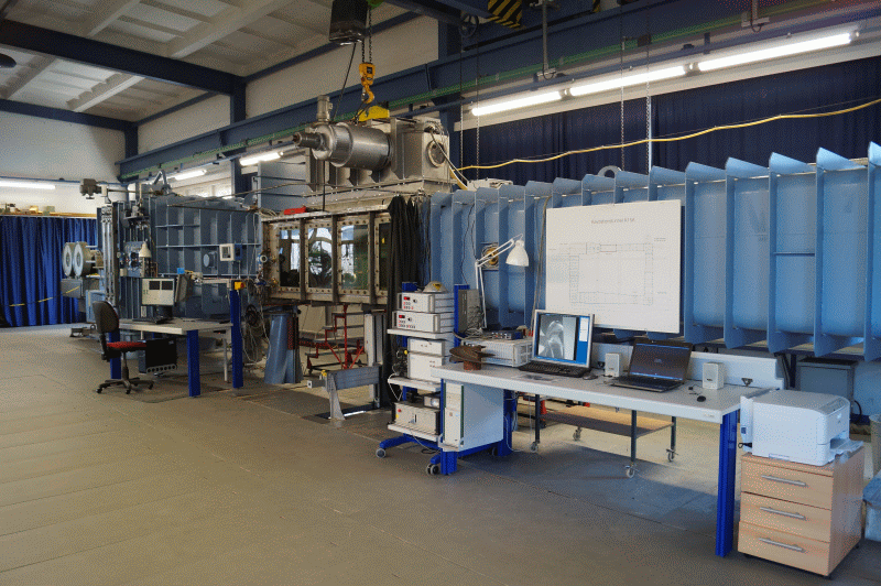
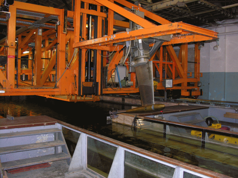
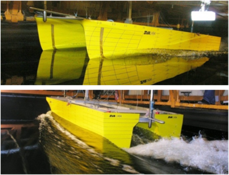
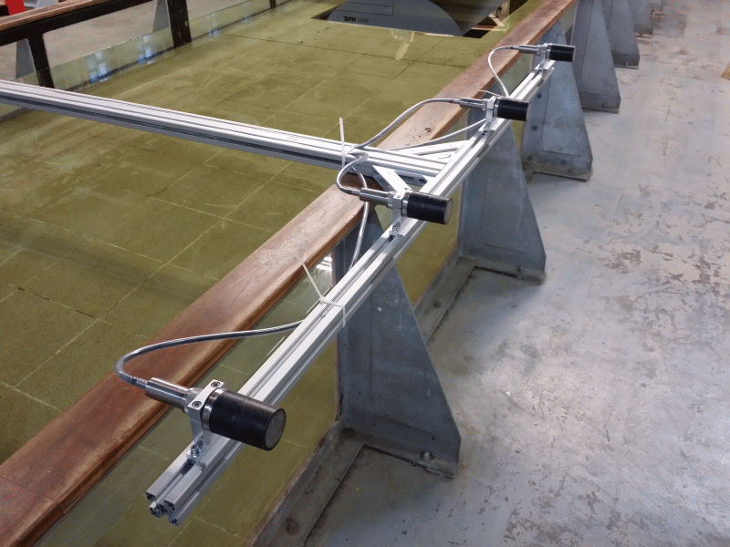
In addition to towing tank pressure pulse measurements, hydroacoustic measurements with a hydrophone line consisting of 16 individual hydrophones are carried out when the ship’s model is passing by [3]. To distinguish and localise sound sources, multiple hydrophones are arranged as an “acoustic camera”. This makes it possible to detect and analyse the noise generation at the bow of a model separately from the propeller-induced noise.

Furthermore, onboard measurements for different issues based on the full-scale ship are offered. In addition to underwater sound, far-field measurements with hydrophones from dinghy, as well as pressure pulse and acceleration measurements on the ship are possible.

Hydroakustik_Foto2_smallHydroakustik_Foto3_smallHydroakustik_Foto1_small


Themenbezogene Referenzen/Forschungsprojekte

[1] Schulze, R.: Hydroakustik, 5. SVA-Forschungsforum, Potsdam, 26. Januar 2012
[2] Klose, R.; Schulze, R.: Körperschallmessungen zur Prognose kavitationsbedingter Erosion an Schiffspropellern, Kolloquium Kavitation und Kavitationserosion, Ruhr-Universität Bochum, 08./09. Dezember 2014
[3] Klose, R.; Schulze, R.: Körperschallmessungen zur Prognose kavitationsbedingter Erosion an Schiffspropellern, 8. SVA-Forschungsforum, Potsdam, 29. Januar 2015
[4] Schulze, R.: Messung des Propulsions- und akustischen Verhaltens am Heavy Lift Vessel „Anne Sofie“ von SAL, Ges. zur Förderung der SVA, Potsdam, 27. Juni 2014

Erosion Test

Bild1_links_Standardkavitator_final
Bild1_rechts_Standardkavitator_final

Cavitation erosion is a kind of material damage which is triggered by certain types of cavitation and can be responsible for deterioration in various areas. Due to the complexity of the process of cavitation erosion, the mechanism behind this action is not yet completely understood.
The risk of erosion of propellers, rudders or appendages is determined mainly by experiment. In the experiments, the erosive effect of the cavitation observed is evaluated and validated by Soft Surface Technique and / or acoustic measurements.
The basis for the erosion tests in the SVA were developed through various R & D projects. In collaboration with the Institute ZWFI “Akademik A.N. Krylov” in Leningrad the Soft Surface Technique was expanded into a method for predicting the erosion intensity [1]. Using this method along with a cavitation generator, parameters of propeller materials (erosion resistance) and erosion coatings were determined. With these values, through experiments, a statement about the risk of erosion and the erosion intensity can be made [2].

In cooperation with the Technical University of Dresden materials were investigated and theoretical methods [3] drawn up to enhance the understanding of the erosion mechanism.

Between 1999 and 2001, with funding from BMBF, the R & D projects “Investigating Layer, Bubble, and Cloud Cavitation and the Associated Erosion Problems” were conducted [4]. During the R & D projects, a new erosion coating was developed and tested in collaboration with the IFL Magdeburg.

Acoustics, which provides another possibility for erosion prediction, is currently being intensively researched as part of the R & D project KONKAV III [5]. Accordingly, erosive cavitation generates different frequency spectra than non-erosive cavitation. On this basis an erosion risk can be detected. The structure borne sound is measured right on the model propeller since the implosion of cavitation bubbles on its surface is responsible for erosion. This kind of erosion detection also offers interesting applications for the real ships on which cavitation monitoring in most cases is very difficult. Based only on the assessment of the frequency spectrum it is possible to determine, without much effort, whether the occurring cavitation is erosive or not.

Bild2_links_Erosion_final1.jpgBild2_rechts_Erosion_final1.jpg


Context Related References / Research Projects

[1] Selke, W., Mehmel, M.: Modellierung der Kavitationserosion an Propellern im Kavitationskanal, Seewirtschaft, 1 0(1978)4
[2] Georgijewskaja, E. P., Mawljudow, M. A.; Mehmel, M.: Entwicklung einer Methode zur Vorhersage der Kavitationserosion an Schiffspropellern, Schiffbauforschung 3(1981)
[3] Bux, K.: Theoretische und experimentelle Analyse der erosiven Wirkung kavitierender Strömungen auf metallische Werkstoffe, Dissertation, Technische Universität Dresden 1987
[4] Heinke, H.-J.: Untersuchung von Schicht-, Blasen- und Wolkenkavitation und der damit verbundenen Erosionsprobleme, 23. BMBF- Statusseminar Entwicklung in der Schiffstechnik, 18. Oktober 2000, Rostock
[5] Klose, R., Schulze, R.: Körperschallmessungen zur Prognose kavitationsbedingter Erosion an Schiffspropellern, Kolloquium Kavitation und Kavitationserosion, Ruhr-Universität Bochum, 08./09. Dezember 2014
[6] Klose, R., Schulze, R.: Körperschallmessungen zur Prognose kavitationsbedingter Erosion an Schiffspropellern, 8. SVA-Forschungsforum, Potsdam, 29. Januar 2015

Pressure Fluctuation Measurement

Druckschw_KT_K15A_2013_c_small
Zeichnung2-Layout1
Besides the main engine, the propeller is the primary cause of ship vibrations. Regarding the formation of the propeller-induced vibrations, two mechanisms of action can be distinguished:

  • Through the work of the propeller in the irregular wake field, periodically fluctuating forces and moments occur which are introduced via the shaft bearings in the hull.
  • The propeller, with its rotating pressure field, generates pulsating compressive forces on the hull. Through the work of the propeller in the irregular wake field additional periodic pressure pulses arise, which can be significantly increased by temporarily occurring cavitation at the propeller blade.

The measurement of the pressure pulses induced by the propeller on the hull of the vessel is accomplished in the large test section (2600 mm x 850 mm x 850 mm) of the cavitation tunnel K15A from Kempf & Remmers [1], [2], [3]. A typical experimental setup for propeller ships is shown. The propeller is driven by the dynamometer H36. Up to 16 pressure sensors are positioned above the propeller in the stern of a dummy model. The length of the dummy models (shortened models with stern contours to scale), is between 2.2 and 2.7 meters. With the dummy model, the predicted three-dimensional inflow to the propeller at the Reynolds number of the vessel is simulated. Within the framework of R & D projects or, for comparison with measurements on ship models, the wake field distribution of the model can be simulated.

Cavitation trials and pressure pulse measurements are based on systematic series of experiments and full-scale measurements to determine and compare the influence of various parameters. The experiments are carried out at high rotational speeds of the propeller model (n > 25 s-1). The oxygen content of the water as a measure of the gas content of the water is controlled at a saturation degree of α / αS > 60%, in order to minimize the influence of the nuclei content of the water and thus the scale effects on the cavitation. In addition, the pressure pulse measurements are performed according to predefined test procedures which, among other things, include a run-in phase of the testing equipment of at least an hour and a range of additional measurements with variations of propeller load and cavitation numbers and variations of the experimental parameters.

The prognosis and simulation of the inflow at the propeller according to the conditions on the ship is a central point of the R & D work on the development of experimental methods for cavitation trials and pressure fluctuation measurements [4], [5]. Therefore, in preparation for the measurements, CFD calculations are performed for the flow around the ship as well as for the flow around the model. Before carrying out the cavitation and pressure pulse measurements, the velocity distribution in the propeller plane of the dummy model will be measured with the LDV system.


Context Related References / Research Projects

[1] Selke, W.; Heinke, H.-J.: Propelleruntersuchungen im Kavitationstunnel der Schiffbau-Versuchsanstalt Potsdam, STG-Jahrbuch 1990
[2] Schmidt, D.; Selke, W.; Gerchev, G.: Comparative Joint Investigations in the Cavitation Tunnels of SVA and BSHC on the Prediction of Propeller Induced Pressure Pulses, Schiffbauforschung 31/1, 1992
[3] Heinke, H.-J.: The Influence of Test Parameters and Wake Field Simulation on the Cavitation and the Propeller Induced Pressure Fluctuations, Jahrbuch der Schiffbautechnischen Gesellschaft, 97. Band, 2003
[4] Heinke, H.-J.; Hellwig-Rieck, K.: Investigation of Scale Effects on Ships with a Wake Equalizing Duct or with Vortex Generator Fins, Second International Symposium on Marine Propulsors, smp’11, Hamburg, Germany, June 2011
[5] Kleinwächter, A.; Hellwig-Rieck, K.; Ebert, E.; Kostbade, R.; Heinke, H.-J.; Damaschke, N. A.: PIV as a Novel Full-Scale Measurement Technique in Cavitation Research, Fourth International Symposium on Marine Propulsors, smp’15, Austin, Texas, USA, June 2015

Cavitation Test


Cavitation tests are carried out in the cavitation tunnel K15A from Kempf & Remmers. The cavitation tunnel has two test sections with cross sections 600 mm x 600 mm and 850 mm x 850 mm and a length of 2.60 m. In the small test section, cavitation tests are predominantly performed with propellers for fast ships and special tests such as measurements on profiles and wings, speed measurements with LDV or PIV, erosion tests, and calibrations of speed measurement systems.

The investigation of the behaviour of propeller cavitation in the wake field of a vessel and measurement of propeller-induced pressure pulses [2] – [6] are carried out in the large test section of the cavitation tunnel. The typical experimental setup for a single-screw vessel is shown in the schematic diagram. The propeller is driven by the dynamometer H36 by Kempf & Remmers. The simulation of the wake, calculated for a Reynolds Number of the full-scale ship, is done with a dummy model and additional grids. The dummy models are up to 2.60 m long and geometrically similar to the ship in the stern area. The blocking of the measuring cross section is within the range between 10 to 22 %. High-Speed recordings of cavitating propulsion systems can be found here.


Context Related References / Research Projects

[1] Potsdam Propeller Test Case: https://www.sva-potsdam.de/en/potsdam-propeller-test-case-pptc
[2] Schmidt, D.: Propellererregte Druckschwankungen an Frachtschiffen mit großen langsamlaufenden Propellern, Schiffbauforschung 26 (1987) 3
[3] Selke, W., Heinke, H.-J.: Propelleruntersuchungen im Kavitationstunnel der Schiffbau-Versuchsanstalt Potsdam, Jahrbuch der STG, 84. Band, 1990
[4] Schmidt, D., Selke, W., Gerchev, G.: Comparative Joint Investigations in the Cavitation Tunnels of SVA and BSHC on the Prediction of Propeller-Induced Pressure Pulses, Schiffbauforschung 31(1992)1
[5] Heinke, H.-J.: Einfluss des Nachstroms auf die Kavitation und Druckschwankungen eines Propellers, 13. SVA-Forum, Potsdam, 29. August 2006
[6] Heinke, H.-J.: The Influence of Test Parameters and Wake Field Simulation on the Cavitation and the Propeller Induced Pressure Fluctuations
Jahrbuch der Schiffbautechnischen Gesellschaft, 97. Band, 2003

Open Water Test

Freifahrt_DiagrammFreifahrt_Test_arrangement_for_open_water_test_small

In open water tests the characteristics of the propeller are measured in homogeneous inflow. Open water tests are mostly performed in the towing tank. For this purpose, the SVA utilises open water carriages and propeller dynamometers. In open water carriage FK1 Kempf & Remmers, the integrated inner dynamometer can be used with different measuring ranges to measure with the highest possible accuracy. In addition, the open water carriage can be used to measure forces and moments on the individual blades of the propeller. For this purpose, measuring hubs have been developed for propellers with three, four and five blades. For the investigation of counter rotating propellers, the dynamometer R40 Kempf & Remmers is used. The dynamometer is installed in the open water carriage FK4 and can be driven by one or two motors to examine the counter rotating propellers with fixed or variable speed ratios. Most open water tests are carried out with the dynamometers H29 and H39 from Kempf & Remmers. The dynamometers differ in size and range and are appropriately selected to match the model propeller.

The characteristics of the propeller can also be determined in the cavitation tunnel K15A. The influence of the limited size of the cross section on the flow velocity or the thrust and torque of the propeller is considered in the test evaluation. The SVA uses the method of Glauert [1] to calculate the wall correction. The cavitation tunnel K15A is equipped with the dynamometers J25 and H36 from Kempf & Remmers. The dynamometer H36 can be used to measure the forces and moments on the individual blades of the propeller by means of a measuring hub.

All dynamometers can be combined with single and three-component balances. Thus, the measurement of the open water characteristics of jet propellers or complex propulsion systems is possible. In addition, two dynamometers and balances can be used together to test counter rotating propellers, tandem propellers or other special propulsion systems.

The shaft inclination of dynamometer H29, H39 and H36 can be varied. The dynamometer H39 and H36 can also be equipped with devices for the measurement of transverse and vertical forces of the propeller.

The detailed description of the experimental procedures and evaluation is contained in the documentation of the Potsdam Propeller Test Case (PPTC) [2].

Freifahrt_K15A_SVA-Potsdam_2015_small


Context Related References / Research Projects

[1] Glauert, H.: Wind Tunnel Interference. W. F. Durand, Aerodynamic Theory, Vol. IV, Berlin 1935, Division L: Airplane Propellers; 296 – 306
[2] smp’11: 2nd Symposium on Marine Propulsors & 1st Workshop on Cavitation and Propeller Performance, June 17 -18, 2011, Hamburg, Germany

Waterjet

Waterjet_einzeln
Waterjet_Propversuche
The main components of the deep submerged water jets (DWJs) are rotor, stator and nozzle. The combination of the rotor and stator ensures a nearly swirl-free jet beam (minimum rotational loss). Through the nozzle geometry, the velocity and the pressure can be influenced within the linear jets (deceleration nozzle) in order to reduce the occurrence of cavitation.

The linear jet is located underneath the ship’s hull. Basic research in the R & D project “Development of Linear Jets for Yachts” [1] showed that the deep submerged water jet is a propulsion system with high efficiency and good cavitation characteristics and can be used, in particular, for fast ships and ships with draught restrictions. During the period from 2000-2005, studies and projects were conducted at the SVA for ships with deep submerged waterjets in collaboration with the industry and manufacturers of waterjets. At the end of 2005, Voith Turbo Schneider Propulsion GmbH & Co. KG [4] (VOITH) took over the development and production of the DWJs renaming them Voith Linear Jets (VLJ). Together with Voith, the R & D project “Development and Optimisation of Deeply Submerged Waterjets” (2006 – 2007) and “Propulsion of Ships with Deeply Submerged Waterjets” (2008 – 2010) were carried out in the SVA [2], [4]. The main goals were the optimisation of the submerged water jets, the determination of the open water characteristics and cavitation characteristics of DWJs, the hydrodynamic integration of DWJs in ship design, the development of the experimental methodology and predicting methods as well as identification of the propulsion characteristics of ships with DWJs. In 2012 VOITH received the first order for a twin set of Voith Linear jets (VLJ) from the British company Turbine Transfer Ltd. for a Wind Farm Support Vessel (WSV). In 2013 the VLJs were developed and manufactured by VOITH. At SVA, systematic experiments [3] and CFD calculations were performed referencing the full-scale measurements from the WSV to check the prediction methods.


Waterjet_im_KT_frontal_smallWaterjet_am_DynamometerWaterjet_Heck_smallWaterjet_im_KT_smallWaterjet_DetailModell_VWJ_small


Context Related References / Research Projects

[1] Bohm, M., Jürgens, D.: LINEAR-Jet: A propulsion system for fast ships, PRADS 1998, The Hague, The Netherlands
[2] Heinke, H.-J., Hellwig; K.: Tiefgetauchter Waterjet – Entwicklungsstand und Ausblick, Marineforum 12/2005
[3] Heinke, H.-J.: Latest Hydrodynamic Results of the Voith Linear Jet, 5th Symposium on Voith Schneider Technology 2014, Heidenheim
[4] Jürgens, D., Heinke, H.-J.: Untersuchung tiefgetauchter Waterjets, STG-Hauptversammlung, Hamburg, Jahrbuch der Schiffbautechnischen Gesellschaft, 100. Band, 2006