Author: pa

CFD-Based Optimisation of a Propeller Wash Deflection Behind an Inland Icebreaker

AdM_Strahlumlenkung_01_small

AdM_Strahlumlenkung_02_small

AdM_Strahlumlenkung_03_small

AdM_Strahlumlenkung_04_small

AdM_Strahlumlenkung_05_small

AdM_Strahlumlenkung_06_small

AdM_Strahlumlenkung_07_small

AdM_Strahlumlenkung_Diag_small

AdM_Strahlumlenkung_Foto_01_small

AdM_Strahlumlenkung_Foto_02_small

AdM_Strahlumlenkung_Foto_03_small

The Schiffbau-Versuchsanstalt Potsdam Potsdam GmbH (SVA) (Potsdam Model Basin) was commissioned by the Special Unit for Mechanical Engineering (FMM) of the Waterways and Shipping Office Minden, to design and calculate a wash deflection behind a ship. The inland icebreaker “Turmfalke” is to be used during the ice-free period, among other things, to stir up and flush the silt deposited on the bottom of the waterways. The propeller wash of the vessel is to be redirected by a device so that the best possible disturbance and resuspension of deposited silt is reached at the water’s bottom. A similar system has already been provided to the client by another company and its successful operation has been repeatedly demonstrated.

The task was divided into 4 work packets: In a preliminary study, a variety of possible baffles were to be fundamentally compared. Then a selected variant would be optimised with regard to its effect on the water bottom. This was followed by the study of the effectiveness at different depths, and the study of various steering flaps to assist manoeuvrability.

Ship and Propeller

Main particulars of the ship
Length between perpendiculars LPP [m] 20.13
Breadth B [m] 7.10 [m]
Draught T [m] 1.40
Displacement [m3] 114.6


With the help of a sea trial protocol of a sister ship, a propeller of the Wageningen B-series was selected which nearly achieves the characteristics of the sea trial. The radial thrust and torque distribution of this propeller was determined by SVA’s own program VORTEX and modelled through an actuator disc within CFD calculations

Deflection Device

The geometry of the deflection device is subject to a few restrictions. The depth of the device should not exceed the ship. Along with that, the feasibility of using simple steel construction methods was looked into.

Constraints

The draught of the ship in the calculations was D = 1.4 m. The water depth was set in the preliminary study and during the optimisation at h = 2.5 m. To determine the effectiveness at other water depths, the effect of wash deflection at h = 2 m, h = 3 m and h = 4 m were calculated. The geometry of the icebreaker was provided by the client. At the location of the propeller a cylindrical region was defined, in which the volume force of the actuator disc was induced. Down below, the calculation area was limited by the water bottom and from above by the surface of the water which was defined as fixed. For the preliminary study a symmetrical situation was adopted (calculation of the half ship / half the region, no twist in the propeller wash) to shorten the calculation time. To optimise the selected variant out of this, the entire flow field was calculated around the ship.

Analysis of the Numerical Simulations

The effect of wash deflection on the water bottom was calculated. The sand roughness of silt soil was assumed k = 0.06 mm (citation in consultation with the client). Through adoption of a fixed bottom, no change in the ground topology by the wash effect could be registered. Above a certain shear stress, a Bingham fluid like slush begins to flow. Therefore, the essential design criterion was the size of the area of the waterway bed where a wall shear stress of τ = 120 Pa is exceeded. As a further assessment criterion, the pressure on the bottom was evaluated.

Comparison of Different Deflections – Preliminary Study

The calculations showed that a side plate is required for effective wash deflection. Through this, the spreading of the wash to the side is significantly reduced. Without a side plate, the required wall shear stress of τ = 120 Pa is not reached. Flow permeable gaps in the deflector should be avoided, as these can substantially reduce the effect of the deflection. The images to the left show the resulting values in dependence of the selected geometry variant (figures 1-6). The closed tunnel variant (figure 6) was the most effective and was selected by the client for optimisation.

Optimization of the Tunnel Variant

For the geometric optimisation of the tunnel, a parametric model was developed for the CAE program “CAESES”. The width of the entry area was set to 1.30 m. In this way, function is guaranteed even with slight rudder deflections. Through the dependency of the geometry on defined parameters, it could be changed fully automatically for optimisation. The vertical position of the upper edge of the tunnel entrance, the height of the entrance area, the length of the tunnel, the ratio of entry area to exit area and the ratio of length-to-width of the exit area were optimised using parametric variation in regard to the resulting bottom surface with a wall shear stress of τ > 120 Pa.

Results of the Optimization

The top of the tunnel is located just below the surface of the water. To prevent the deflected wash from flowing over, the area between the ship and deflection device should be covered at the surface of the water. The breadth of the water bottom area experiencing a wall shear stress of τ > 120 Pa is about 2.5 m, the length is about 2 m. The wall shear stress and the pressure at the water bottom which are generated by the optimum tunnel variant is shown in figure 7. To demonstrate the effectiveness of the optimised tunnel geometry at different water depths, additional calculations at h = 2, 3 and 4 m were performed. The results show a moderate decrease in the effectiveness depending on the water depth. At 4 m water depth 120 Pa wall shear stress is no longer achieved (see graph in figure 8).

Evaluation of the Results

Because of the applied simplifications (fixed water surface, quasi-static calculations, actuator disc, no change in the ground topology) the results may only be qualitative. The pressure on the water bottom corresponds to 28.000 Pa (N/m^2) at a depth of h = 2.5 m. Such pressure should lead to a deformation of mud at the water bottom (washed out cavity) which will again significantly increase the flushing effect.

Comparison of Theory (SVA Simulations) and Practice (Trial Run, see below)

The optimisation of the device was carried out at a low system speed, because the self propulsion point was achieved in the calculations with PMotor = 2/3 PMotor max below 5 km/h. However, the device appears to produce a significantly lower resistance in reality. This suggests that the specification of a “fixed” water surface – despite a plate between tunnel entrance and ship – is not optimal under these circumstances. In operation, the device would clearly be washed over. To reduce the speed, the propeller wash is to be restricted in the future through additional lateral plates.

Real-World Implementation of the Wash Deflector

All following contents shown were edited by the company “TECHNOMAR GmbH & Co. KG” and provided to SVA through the Special Unit for Mechanical Engineering (FMM) of the Waterways and Shipping Office Minden from the sea trial protocol.

Manoeuvring Behaviour

The ship carries out rudder manoeuvres reliably. Also, no problems arise when reversing. The device reduces the boat speed under full load from 15 km/h to 12 km/h. The skipper states: “A safe manoeuvring is possible. There are no restrictions.”

Reviewing the Effectiveness

The provided test course has been driven through and the water depths read. The water depth is 2.4 m on average. Then, a distance of 400 to 500 m is covered in a total of 3 runs with steps of different speeds. Through the flushing process the whirling water came to the surface and was deep black with sediments. After the 3rd passage gas bubbles (fermentation gases) were shown on the surface. The experiment was ended and the device taken out of the water. The test course was driven again and the water depth determined. It was now measured at around 2.80 m. The waterway course was deepened in this experiment by about 40 cm. The thrust vectoring device must now be tested in further experiments on the effectiveness of the flushing. This is carried out and documented by the WSA-Meppen. All participants believe that the device is an improvement in controlling the silt problem on the Ems River.

Courtesy of:

Fachstelle Maschinenwesen Mitte
at Minden Waterways and Shipping Office
Am Hohen Ufer 1-3
32425 Minden

Author: Dipl.-Ing. E. Schomburg

Open Water Test Dynamometer

Main Parameter
H29 H39
Propeller thrust T<max [N] 400 1000
Propeller torque Qmax [Nm] 15 55
Propeller R.P.M. nmax [s-1] 60 60
Max. Propeller Shaft Inclination [°] 30 30


Main Parameter
R25 R31 R73 R40
Propeller Thrust Tmax [N] 100 250 600 150
Propeller torque Qmax [Nm] 4 10 30 6
For propeller open water tests in the towing tank the following dynamometer types are mainly used: H29 and H39 from Kempf & Remmers. Both dynamometers measure the thrust and torque of the propeller. On both devices, a measuring balance for the thrust nozzle can also be mounted. The H39 can be equipped with a shaft which permits the measurement of the lateral forces of the propeller.

The dynamometers are capable for experiments with shaft inclination.

Open Water Carriages FK1, FK4

The open water carriages FK1 and FK4 offer the possibility to perform tests with internal propulsion dynamometers for ship models. Custom dynamometers from Kempf and Remmers are used for the measurement range and for the FK4 carriage, the counter rotating dynamometer R40 from Kempf & Remmers is used. A measurement balance for nozzles can also be mounted on both devices.

FF_Rinne_H39a_smallFF_H39c_smallFF_FK1_smallFF_FK4_small

Shallow Water

CFD_flachw_karte_m_Rahmen

CFD_flachw_diag_wellenbilder_m_Rahmen

Shallow water has a significant influence on the handling of ships. The most obvious effect is the changing shape of waves in shallow water. Due to the different wave propagation and wave group velocities of deep and shallow water at the same wave length, the interaction between the different wave systems of a ship changes. This is manifested, among other things, through strong changes in KELVIN angle.

To illustrate the shallow water effects the Froude depth number is generally used; wherein the driving regimes are subvided in a subcritical (Frh < 0.9), critical (0.9 < Frh < 1.1) and a supercritical (Frh > 1.1) ranges. Normally, ships operate in the subcritical range. For critical Froude depth numbers, a strong increase in resistance and a large change in the dynamic flotation position can be expected depending on the ship type since, in this region, the transverse waves move at the speed of the vessel. As a special case, soliton waves can occur in this area. In the case of supercritical Froude depth number, the ship is faster than the maximum wave speed and the transverse waves disappear in the secondary wave system.

Numerical methods have extensive applications in the calculations of shallow water effects.

  • Calculation of the resistance and the flotation position at varying depths, velocities and ground topologies
  • Calculation of waves / wave heights on banks and shores.

The SVA uses ANSYS CFD for this.

Fast moving ships are more affected by shallow water effects than slow moving ships. The areas of the Baltic Sea are represented in the image below for three different speeds where the vessel would be running in a critical Froude depth number (0.9 <Frh<1.1) speed range. Near the coast the boat is moving in supercritical range, further out on the Baltic Sea in the subcritical Froude depth number speed range.


CFD_flachw_wavecontours_m_RahmenCFD_flachw_widerstand_flachw_m_RahmenCFD_flachw_5_wavesystems


Context Related References / Research Projects

[1] Nietzschmann, T.: Untersuchungen zum Widerstandsverhalten von schnellen Schiffen bei veränderter Bodentopologie, 6. SVA-Forschungsforum „Theoria cum praxi“, Potsdam, 31.01.2013
[2] Lübke, L.: Fast Ship Hydrodynamics on Shallow Water, 8th International Conference on High-Performance Marine Vehicles (HIPER), Duisburg 27. – 28.09.2012

Ducted Propellers

Düsenprop_test DP_Kavitation_small

Düsenprop_Profilformen

Düsenprop_CFD_Hinterschiff

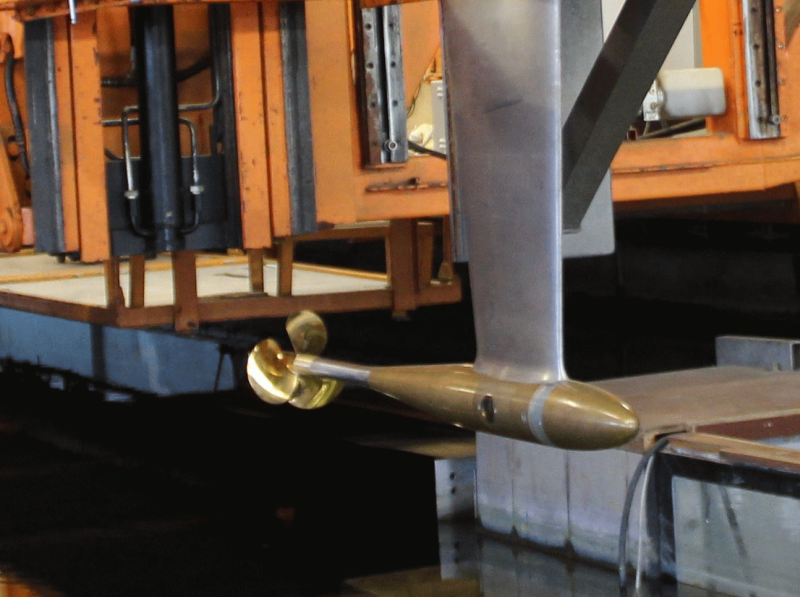
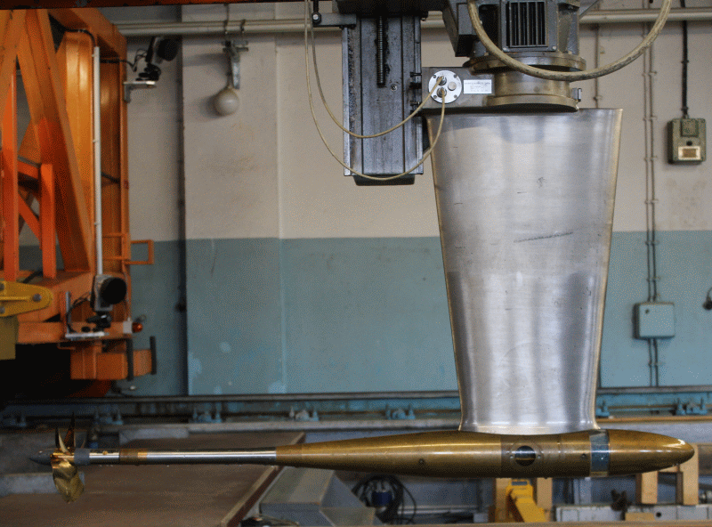
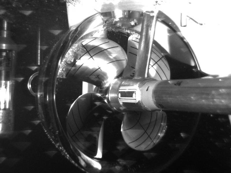
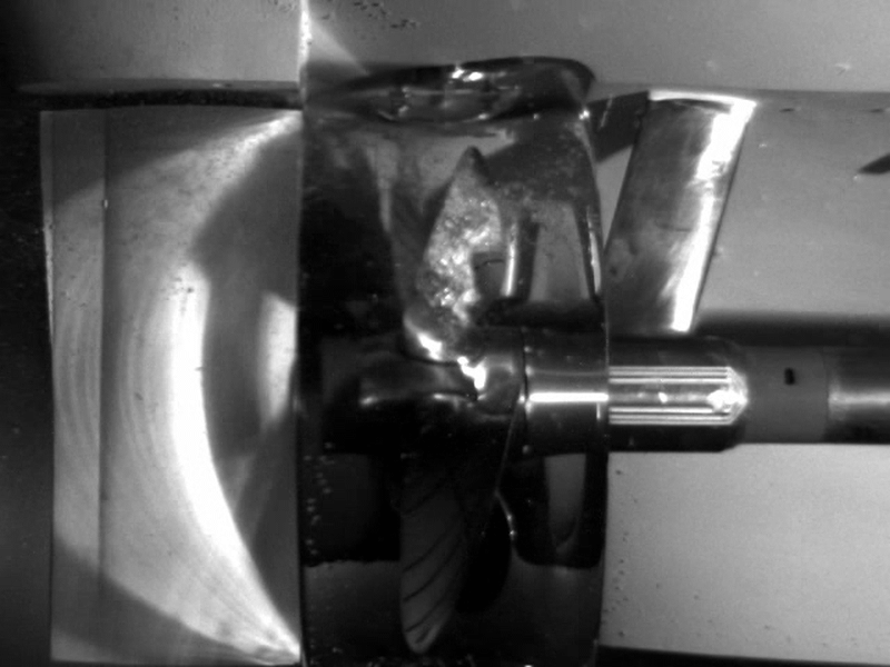
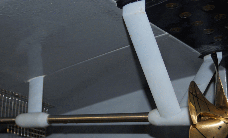
A nozzle is a hydrodynamically optimised shell encircling the blade tips of a propeller. The combination of propeller and nozzle is called a ducted propeller. There are two types of nozzles, the acceleration and the deceleration nozzle. The deceleration nozzle causes a reduction in flow velocity and an increase in pressure in the propeller plane. Deceleration nozzles are therefore used to reduce the cavitation risk for fast ships.

The accelerating nozzle causes an increase in flow velocity and hence a discharge of the propeller. Ducted propellers with an acceleration nozzle are used for highly loaded propellers and propellers with restricted diameters.

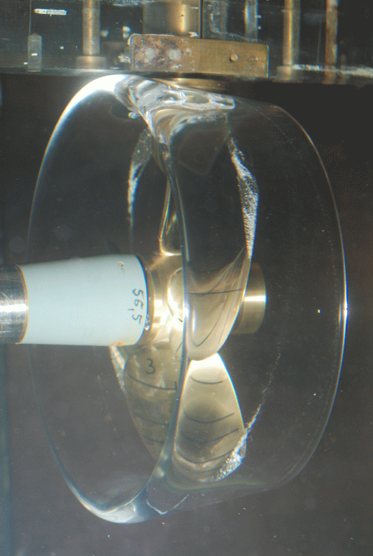
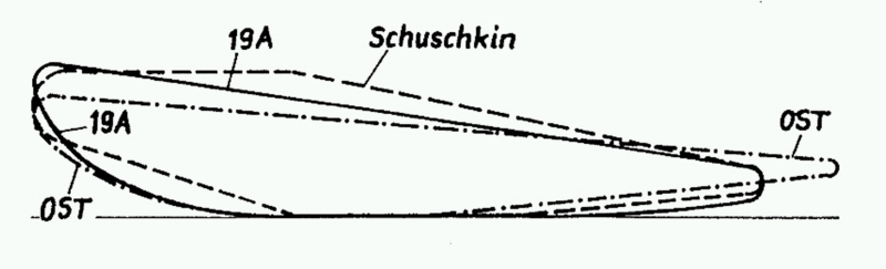
Since its foundation in 1953, the SVA Potsdam has been working on the development and optimisation of ducted propellers for inland and fishing vessels as well as tugs as well as thrusters. In addition to conventional ducted propellers (Wageningen, Schuschkin, OST), unconventional, partially integrated nozzle and controllable pitch propellers have been studied extensively in particular.

Based on a series of tests in the context of an R & D project with a combination of propellers of the Wageningen B-series and OST nozzles, polynomial coefficients were developed for ducted propeller systems with OST nozzles [10]. At lower thrust loads, the OST nozzle profile increases the mass flow through the propeller disc and causes a jet expansion at the nozzle outlet. The characteristics of ducted propellers with OST nozzles can be calculated with polynomial coefficients and used for propulsions prediction.

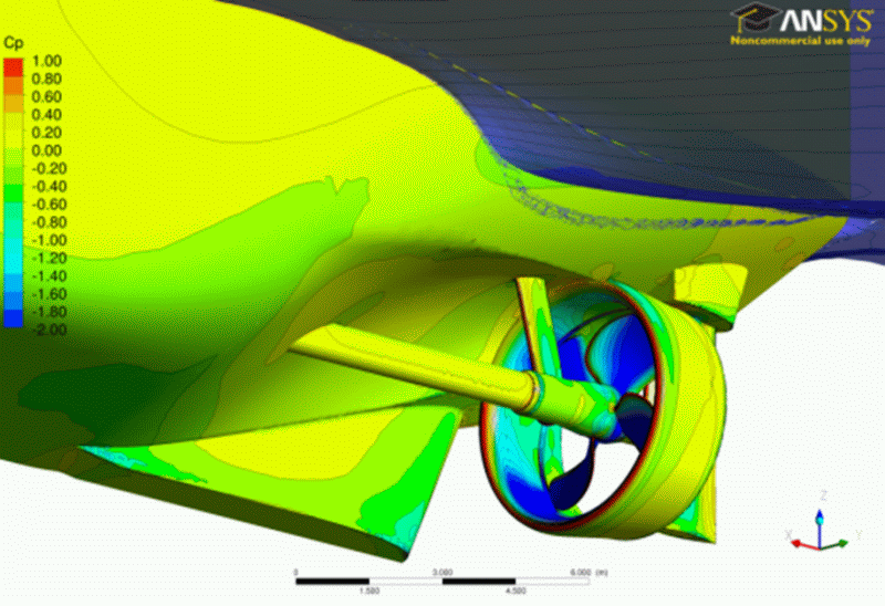
In the field of CFD calculation, research projects were conducted in close cooperation with ANSYS Germany GmbH for ducted propeller calculation. Based on the developed methods, systematic numerical calculations of ducted propellers were implemented in the R & D project “Correlating Z-Drives with Nozzles” to develop a method for Reynolds number correction (conversion of model test results to the full-size version).

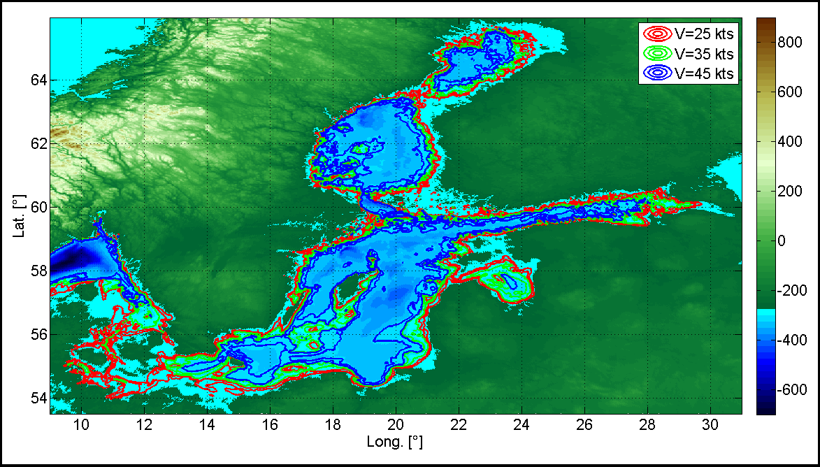
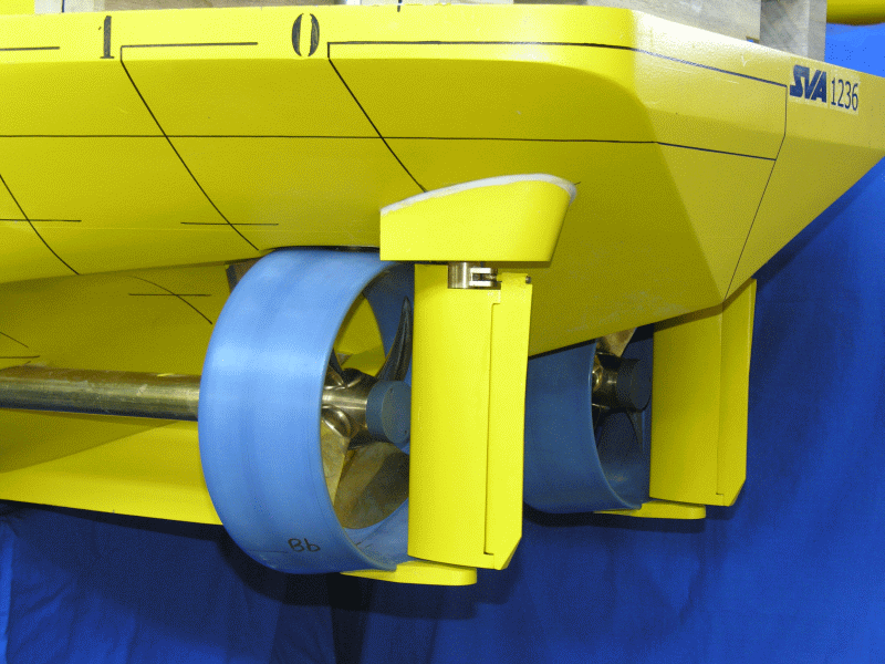
The continued development and validation of the bollard pull and propulsion prediction for tugs with large power capacity has been the subject of R & D projects and industry projects. In the R & D projects “Increasing the Design Safety of Ducted Propeller Systems at Bollard Pull Conditions” and “Reynolds Number Effects on Bollard Pull Predictions” [5], [6] the influences of cavitation and scale on the bollard pull of tugs with ducted propellers were presented in detail. With these results, the risk of thrust break down of ducted propeller can be found in the design stage.

In the R & D project “Forecasting Reliability for the Power Requirement of Tugs with Ducted Propeller Systems”, GeoSim tests and calculations were carried out for tugs at the point of propulsion. The results of these studies have been incorporated into the propulsion forecasting methods for ships with ducted propellers.

Düsenprop_M1236Z010_small

Düsenprop_Schubabfall_Diag

Düsenprop_Wagening_Diag

Düsenprop_Figure18-left_small

Düsenprop_Figure18-right_small


Context Related References / Research Projects

[1] Abdel-Maksoud, M.: Convergence Study of Viscous Flow Computations Around a High Loaded Nozzle Propeller, Numerical Towing Tank Symposium NuTTS 2000, Tjärnö, Sweden, September 2000
[2] Abdel-Maksoud, M., Heinke, H.-J.: Scale Effects on Ducted Propellers, 24th Symposium on Naval Hydrodynamics, Fukuoka, Japan, July 2002
[3] Gutsche, F.: Düsenpropeller in Theorie und Experiment, Jahrbuch der STG, Bd.53, 1959
[4] Heinke, H.-J., Philipp, O.: Development of a skew blade shape for ducted controllable pitch propeller systems”, Proceedings, PROPCAV’95, Newcastle, 1995
[5] Heinke, H.-J., Hellwig, K.: Aspekte der Pfahlzugprognose für Schlepper großer Leistung, 104. Hauptversammlung der STG, Hamburg, November 2009
[6] Mertes, P., Heinke, H.-J.: Aspects of the Design Procedure for Propellers Providing Maximum Bollard Pull, ITS 2008, Singapore, May 2008
[7] Philipp, O., Heinke, H.-J., Müller, E.: Die Düsenform – ein relevanter Parameter der Effizienz von Düsen-Propeller-Systemen, STG-Sprechtag „Hydrodynamik schneller Schiffe und ummantelter Propeller“, Berlin, Potsdam, September 1993
[8] Philipp, O., Heinke, H.-J., Binek, H.: Contribution of Hydrodynamics for the Calculation of Ducted Units for Ships at Shallow Water, HYDRONAV’ 95, Gdansk, November 1995
[9] Schroeder, G.: Wirkungsgrad von Düsenpropellern mit unterschiedlicher Düsen- und Propellerform, Schiffbautechnik 17 (1967) 8
[10] Schulze, R., Manke, H.: Propellersysteme mit Ostdüsen, HANSA, 137 (2000) 2

Open Water Manoeuvrability Testing

Investigations on manoeuvring behaviour that cannot be carried out at the testing facilities of the SVA because of the limited space and high speed occur in the field. The model’s behaviour is detected via a GPS system and by a LASER-optic gyroscope. All the necessary manoeuvres can be either manually or automatically controlled. In addition, so-called source manoeuvres are carried out in order to derive the mathematical model by means of a movement identification system.


freilandversuch2_galerieFreiland_2


Context Related References / Research Projects
[1] Steinwand, M.: System identification of manoeuvring ship models, SVA-CTO-Meeting, Juni 2004
[2] Steinwand, M.: Optimierung des Stoppmanövers von Schiffen mit Verstellpropellern und Hybridantrieben, 9. SVA-Forschungsforum „Theoria cum praxi“, Potsdam, Januar 2016

3D Printer

3D_Drucker_Drucker

3D_Drucker_Wellenbock_small

The Eden350V 3D printer is available for the manufacture of components with complex geometries and very small tolerances. It builds synthetic material up in 16 micron layers which are cured by UV light. This method enables the manufacturing of objects of any geometry with the highest precision.
Technical data
Max. component length x axis [mm] 340
y axis [mm] 340
z axis [mm] 340
Resolution Layer thickness [µm] 16
x axis [dpi] 600
y axis [dpi] 600
z axis [dpi] 1600
Accuracy Components >= 50 mm [µm] 200
Components < 50 mm [µm] 20…85