Within the scope of the project, the influence of pre-swirl ducts (PSD) on the manoeuvring behaviour of complete ships, in particular the course stability, and the interaction of the pre-swirl duct with rudder and propeller will be investigated. Continue reading “PSDMan
(07/2019 – 06/2022)”
Author: pa
PSDMan
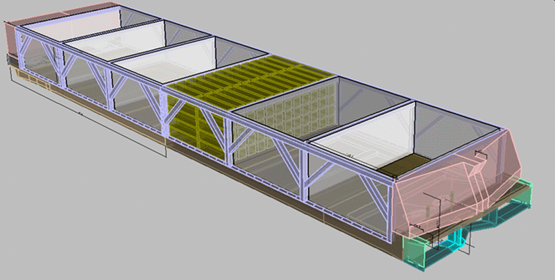
Outdoor Model Tests for the Evaluation of the Manoeuvrability of an „Inland Waterways Container Ship“
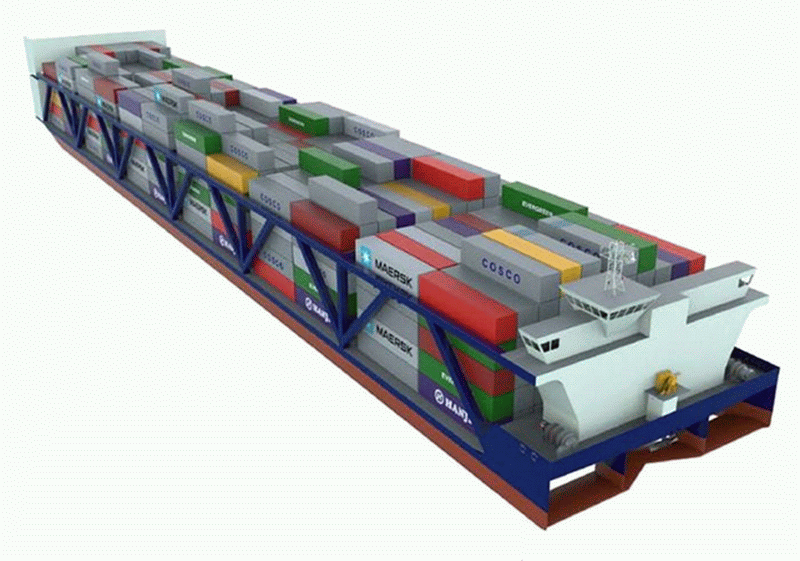
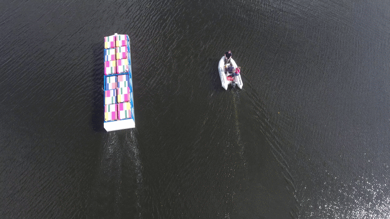
As part of an industrial project for the American Patriot Holdings LLC (APH) dealing with a new concept of an inland waterways container carrier (designed by NaviForm Consulting & Research), outdoor manoeuvring tests were conducted to complement the standard resistance and propulsion tests.
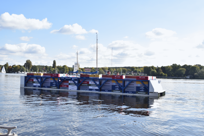
The manoeuvring tests were performed in a sheltered little bay of the Berlin part of the river Havel in the city of Spandau. The approximately 9 m long ship model (scale: 20) was manufactured at SVA Potsdam and, in accordance to NaviForm specifications, equipped with modelled superstructures and stylized containers. The ship was propelled by 4 VSPs, of which 2 were used solely for propulsion and the others mainly for manoeuvring purposes. The drives were provided by Voith Turbo GmbH & Co. KG. In the manoeuvring tests straight line, turning on the dime, turning circle and dock moving sidewise tests were conducted.
The tests were performed for a single draught. The thrust distribution scheme for the 4 drives which was identified as the best during previously conducted towing tank tests was also used in the outdoor tests. For full scale speeds of 8 kn and 12 kn straight line and turning circle manoeuvres were demonstrated.
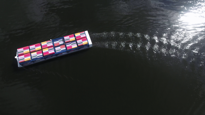
The model tests were documented with video recordings. Beside a stationary camera a quadrocopter drone was used that provided recordings from different views of the manoeuvring behaviour of the ship.
The results showed that the targeted speed of 12 kn in straight line test could easily be achieved with the optimized thrust distribution scheme for the 4 VSPs. A turning circle with a diameter of less than 7 ship lengths can be achieved for a velocity of 8 kn and a thrust direction of 10°. At 12 kn the diameter of the turning circle spans about 7 ship lengths.
Due to the utilization of a purpose built wing system at the ship’s bow a considerably reduced wave system could be observed even at a speed of 12 kn.
In general a very good manoeuvring performance could be demonstrated for this inland waterways container carrier.
Author: Dr.-Ing. Matthias Fröhlich, Schiffbau-Versuchsanstalt Potsdam GmbH
Friction Measurements of Different Coatings in a Friction Tunnel
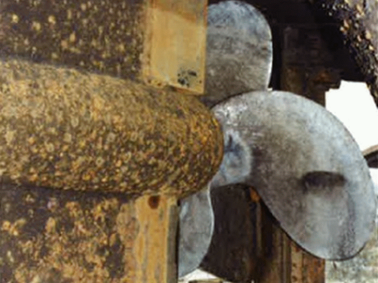
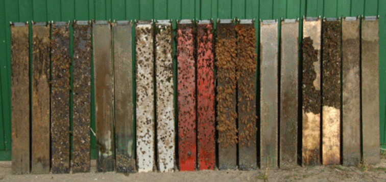

It is well known that the frictional resistance of a ship is a substantial part of its total resistance (around 25 up to 75 %). This is mainly influenced by the surface texture of the hull skin, which depends for example on the coating or on the degree of fouling. With respect to power consumption reduction it therefore can be meaningful to minimise the frictional resistance by applying special coatings or surface textures. The requirements for these coatings are low friction and anti-fouling properties as well as long service times and resistance to mechanical impacts regarding ice, tugs or fenders. With the help of the friction tunnel of the SVAtech the friction characteristics of these coatings can be measured. Long term tests give answers how fouling and imperfections affect the friction characteristics of the coating.
The frictional resistance of a one-sided wetted flat plate is well known from semi-empirical investigations. There are several formulas for laminar and turbulent flow, developed by e.g. Blasius, Prandtl, Schönherr, Schlichting/Gersten, etc. For Schlichting/Gersten also the roughness of the surface is included, but when dealing with complex surface structures a mere roughness consideration is not enough.
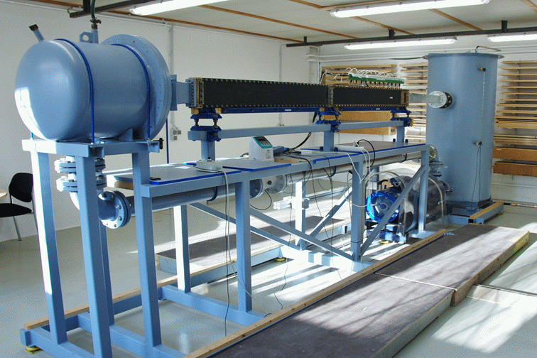
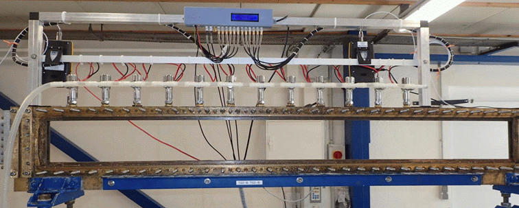
In this case, measurements as with SVAtech’s friction tunnel are still meaningful for providing reliable results in an easy way. Put simply, the friction tunnel is a small water circuit tank in which plates with the coating to be investigated can be installed. Therefore two of these plates form a narrow rectangular channel for which the wall shear stress inside can be derived from the pressure loss between several observation points. In SVAtech’s friction tunnel 12 equidistant positions over the length of the test plates are used for measuring the pressure drop. Finally, the friction coefficient is obtained by dividing the wall shear stress by the dynamic pressure.
The friction tunnel was developed in 1992 at the Research Institute for Hydraulic Engineering and Shipbuilding (Versuchsanstalt für Wasserbau und Schiffbau) in Berlin and was property of the Technical University from Berlin for a long time until in 2004 SVA bought it. To reach the high accuracy demands of the customers several modifications were necessary. The test section was extended to 12 pressure sensors and a venting valve for each pressure sensor to ensure that no air bubbles are trapped inside the circuit. A magnetic inductive flow meter helps determining the water velocity in the test section. There is a choice of two different flow meters (one covering the small and one the high water speed ranges). Furthermore, 2 temperature sensors were installed to determine the water properties like density and viscosity. A microprocessor automatically runs the engine control of the pump and conducts the calculation of the fitted pressure gradient and friction coefficient. The data is transferred to a computer where the final evaluation is done.
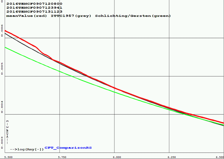
The test procedure is fully automated in such a way that the whole speed range from 1 m/s up to 18 m/s (or respectively log(Re) = 5.4 up to 6.7) is measured in 26 steps three times. For each step there is a waiting time of 60 s for the stabilization of the flow and finally 15 s of measurement time. In the end the mean value curve of all three runs is calculated.
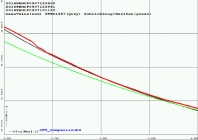
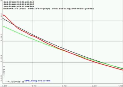
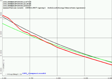
The usual way to present the results of friction measurements is in dependency of the Reynolds number. The challenge is to make the channel flow comparable with a flow around a body as for ship applications. The solution is to determine experimentally the reference length for the calculation of the Reynolds number in such a way that it equals a flow around a body. With the resulting reference length (which is almost the channel perimeter) a good accordance with the ITTC’57 curve is reached for technically smooth plates.
For textures a presentation over s+ can be more meaningful than the Reynolds number. The s+ value is the dimensionless characteristic length for one structure element, e.g. for riblet structures it is the distance of two riblets.
Different measurements were carried out. Good results were achieved with the former anti-fouling spray “Biotard”. For a wide range of Reynolds numbers the friction coefficient is slightly lower than that of the smooth plate. A bigger effect is visible when using riblets which – in a defined s+ range – can cause a significant reduction of the friction. During the investigations of riblet structures the idea came up to test “simple” riblets made by hand with sandpaper and a belt grind. The resulting structure is similar to the perfect riblet structure. The maximum friction reduction is not as big as for the perfect riblets but the Reynolds number range is wider for which the friction is lower than that of a smooth plate.


But it must not be forgotten that not only the “fresh” coating has to be investigated. It is also important to test the long term qualification after several months of operation. SVAtech simulates this in cooperation with the Laboratory LimnoMar where the test plates are exposed to the North Sea for a certain period of time. After this time the plates are tested again in the friction tunnel.
In summary, the friction tunnel provides friction characteristics of different coatings and textures in an easy and cheap way. The real surface and not only a model of it can be measured over a wide range of Reynolds number. A quick answer regarding the drag reduction and hence fuel savings can be given. The measurements are applicable for a wide field not only in the shipbuilding industry but also for the aerospace or automotive industry.
Author: M. Sc. Rhena Klose, Schiffbau-Versuchsanstalt Potsdam GmbH
The full text can be found in:
R. Klose, R. Schulze: Friction Measurements of Different Coatings in a Friction Tunnel, Proceedings 2nd Hull Performance & Insight Conference, 2017
Calculation Method for the Design of Roll Damping Tanks


Within the framework of the research project ROLLTANK sponsored by the BMWI, a method for improving the determination of the flow processes in roll damping tanks was developed. The improved design of this type of installation can be used with a view to an optimum seakeeping behavior of a ship. The method development was supported by accompanying laboratory tests. In addition to investigations of a laboratory model of a RoPax vessel in the towing tank, further useful data for the validation of the method to be developed was provided through the use of a modified roll system with an electric drive for the excitation of a roll damping tank, isolated from the vessel, to defined sinusoidal vibrations.
Two Frahm tanks and a box tank were designed for testing on the roll system. The experimental program included measurements with sinusoidal excitation, variation of the frequency, roll amplitude, and the fill level of the tank. Differing variants of internals within the tanks were taken into account. The evaluation of the measurements was supported by video recordings and the use of ultrasound probes.
The laboratory tests were carried out in the towing tank with specially designed Frahm and Box tanks with variation of metacentric height, wave height, wave length as well as the sea state in regular and irregular seas. In order to ensure defined boundary conditions for the validation, the tests were carried out in beam seas without any speed.
For further evaluation of the laboratory tests and process development, RANSE calculations were performed for selected cases.
The starting point for the method to be developed was the Morison equation, which was expanded with respect to the parts of a developed vortex system proportional to speed and acceleration. As a result, coefficients of resistance and damping are supplied which then are corrected with empirical formulas depending on the obstruction in the tanks. In the further development, shallow water equations were used, which were extended for the developed non-linear parts. These equations formed the basis for subsequent non-linear tank calculations using the nonlinear strip method ROLF. To this end, the ROLF method was extended with additional tools for tank calculation, which distinguishes it from the STRIP method (linear strip method form the software system UTHLANDE). Extensive simulations were carried out using the new method and were compared with the results of the laboratory tests for their validation.
Extensive validation and comparison with previous methods show that the implementation of the new method in ROLF allows a fast and efficient prediction of the roll damping effect of the tank, especially in the case of large roll amplitudes. For the first time, and in contrast to the STRIP method, effects of parametric roll excitation of ships with roll damping tanks can also be determined. The use of the method for projects in the shipbuilding industry is therefore sensible in areas where minimal roll movements of the ship during operation are important even in extreme seas to minimize the risks to crew and ship. In addition to passenger ships and yachts, the future market is being seen in applications for offshore industrial projects. These include work boats and supply vessels for wind power and offshore installations, where it must be possible to come alongside and land in strong sea states. Lastly and importantly, the use of the procedure contributes to advances in ship safety.
Author: Dr.-Ing. Matthias Fröhlich, Schiffbau-Versuchsanstalt Potsdam GmbH
.")


Propeller Manufacturing
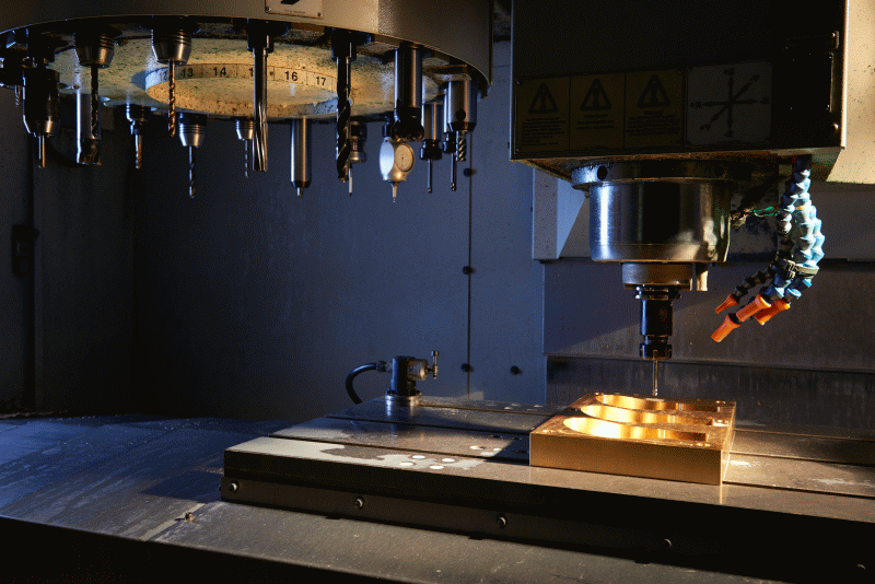
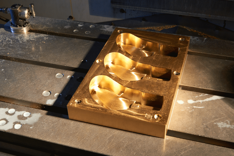
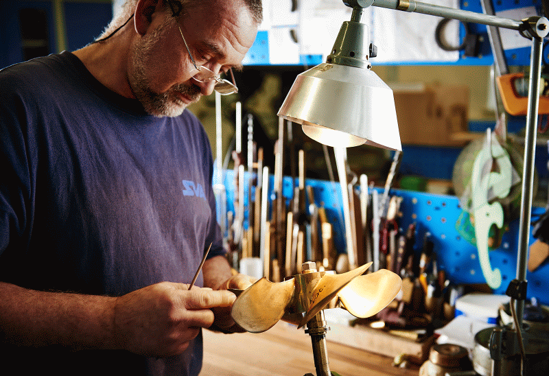
Various machines are available for the manufacture of propellers, appendages and accessory parts.
Automatic Cycles Lathe UT500
For the production of swivel parts (small batches and individual parts) the automatic cycles lathe UT 500 is available. Through the possibility of free-form programming, for example, propeller nozzles, outlets and other parts that are not purely cylindrical can be produced quickly and efficiently on this machine.
Main Paramaters Automatic Cycles Lathe UT500 |
||
| Swing Diameter over Bed | [mm] | 510 |
| Swing Diameter over Cross Slide | [mm] | 340 |
| Swing in Bed Bridge | [mm] | 760 |
| Distance Between Centers | [mm] | 1500 |
| Vertical Travel Distance | [mm] | 680 |
| Max. Turning Length | [mm] | 1140 |
| Travel distance bed Bridge (x axis) | [mm] | 310 |
5 Axis Milling Machine UNITECH XV620-5AX
A XV 620-5AX 5-axis milling machine is available for machining of complex components such as model propellers, shaft struts and propeller hubs. The machine has a working area of 650 x 520 x 480 mm³ with a drive power of 10 kW and is well established in the field of precision engineering.
Main Parameters Milling Machine UNITECH XV620-5AX |
||
| x-Axis (Longitudinal Adjustment) | [mm] | 620 |
| y-Axis (Lateral Adjustment) | [mm] | 520 |
| z-Axis (Support Vertical Adjustment) | [mm] | 510 |
| Tool Fitting (DIN 69871) | — | Taper Shank SK40 |
| Input Power at S1 100% | [kW] | 10 |
| Torque at S1 100% | [Nm] | 64 |
| RPM Range | [min-1] | 0 …12000 |
Milling Machine UNITECH VMC1200
The UNITECH VMC1200 milling machine serves to produce components made of metal. This is characterised by its large working area of 1000 x 520 x 480 mm³. The 4th axis, simultaneously controlled, attachments allow for the production of components (drive housings) that must be pivoted during processing.
Main Parameters Milling Machine UNITECH VMC1200 |
||
| x-Axis (Longitudinal Adjustment) | [mm] | 1000 |
| y-Axis (Lateral Adjustment) | [mm] | 520 |
| z-Axis (Support Vertical Adjustment) | [mm] | 420 |
| Tool Fitting (DIN 69871) | — | Taper Shank SK40 |
| Input Power at S1 100% | [kW] | 16 |
| Torque at S1 100% | [Nm] | 60 |
| RPM Range | [min-1] | 0 …15000 |
CFD-Based Optimisation of a Propeller Wash Deflection Behind an Inland Icebreaker
The Schiffbau-Versuchsanstalt Potsdam Potsdam GmbH (SVA) (Potsdam Model Basin) was commissioned by the Special Unit for Mechanical Engineering (FMM) of the Waterways and Shipping Office Minden, to design and calculate a wash deflection behind a ship. The inland icebreaker “Turmfalke” is to be used during the ice-free period, among other things, to stir up and flush the silt deposited on the bottom of the waterways. The propeller wash of the vessel is to be redirected by a device so that the best possible disturbance and resuspension of deposited silt is reached at the water’s bottom. A similar system has already been provided to the client by another company and its successful operation has been repeatedly demonstrated.
The task was divided into 4 work packets: In a preliminary study, a variety of possible baffles were to be fundamentally compared. Then a selected variant would be optimised with regard to its effect on the water bottom. This was followed by the study of the effectiveness at different depths, and the study of various steering flaps to assist manoeuvrability.
Ship and Propeller
Main particulars of the ship |
||
| Length between perpendiculars | LPP [m] | 20.13 |
| Breadth | B [m] | 7.10 [m] |
| Draught | T [m] | 1.40 |
| Displacement | ∇ [m3] | 114.6 |
With the help of a sea trial protocol of a sister ship, a propeller of the Wageningen B-series was selected which nearly achieves the characteristics of the sea trial. The radial thrust and torque distribution of this propeller was determined by SVA’s own program VORTEX and modelled through an actuator disc within CFD calculations
Deflection Device
The geometry of the deflection device is subject to a few restrictions. The depth of the device should not exceed the ship. Along with that, the feasibility of using simple steel construction methods was looked into.
Constraints
The draught of the ship in the calculations was D = 1.4 m. The water depth was set in the preliminary study and during the optimisation at h = 2.5 m. To determine the effectiveness at other water depths, the effect of wash deflection at h = 2 m, h = 3 m and h = 4 m were calculated. The geometry of the icebreaker was provided by the client. At the location of the propeller a cylindrical region was defined, in which the volume force of the actuator disc was induced. Down below, the calculation area was limited by the water bottom and from above by the surface of the water which was defined as fixed. For the preliminary study a symmetrical situation was adopted (calculation of the half ship / half the region, no twist in the propeller wash) to shorten the calculation time. To optimise the selected variant out of this, the entire flow field was calculated around the ship.
Analysis of the Numerical Simulations
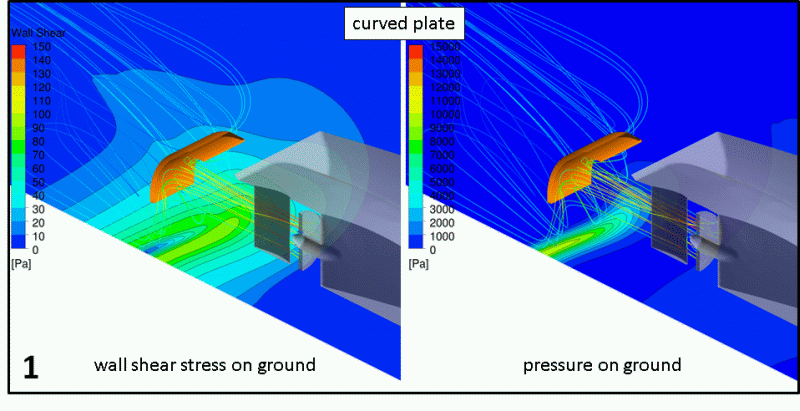
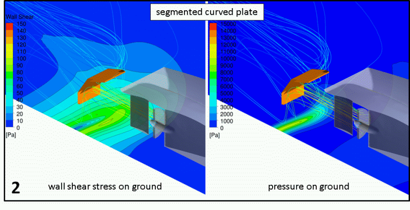
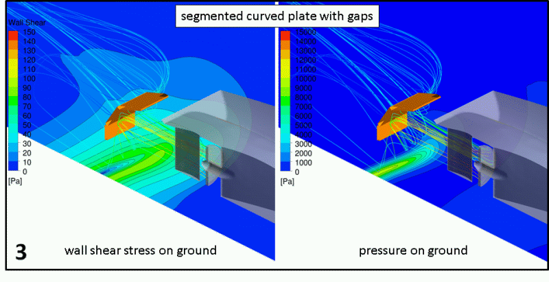
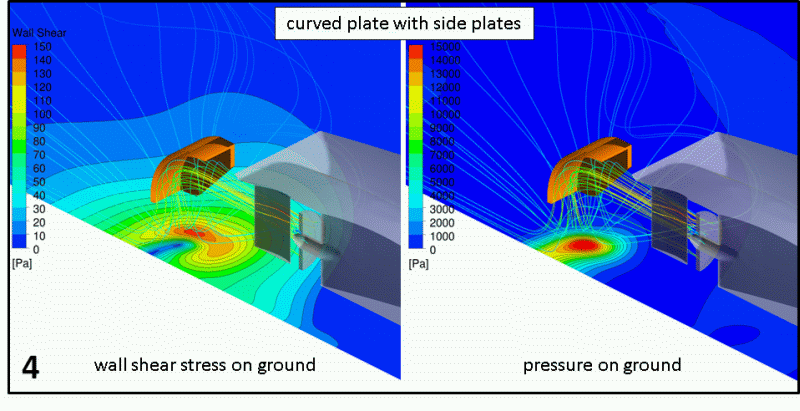
The effect of wash deflection on the water bottom was calculated. The sand roughness of silt soil was assumed k = 0.06 mm (citation in consultation with the client). Through adoption of a fixed bottom, no change in the ground topology by the wash effect could be registered. Above a certain shear stress, a Bingham fluid like slush begins to flow. Therefore, the essential design criterion was the size of the area of the waterway bed where a wall shear stress of τ = 120 Pa is exceeded. As a further assessment criterion, the pressure on the bottom was evaluated.
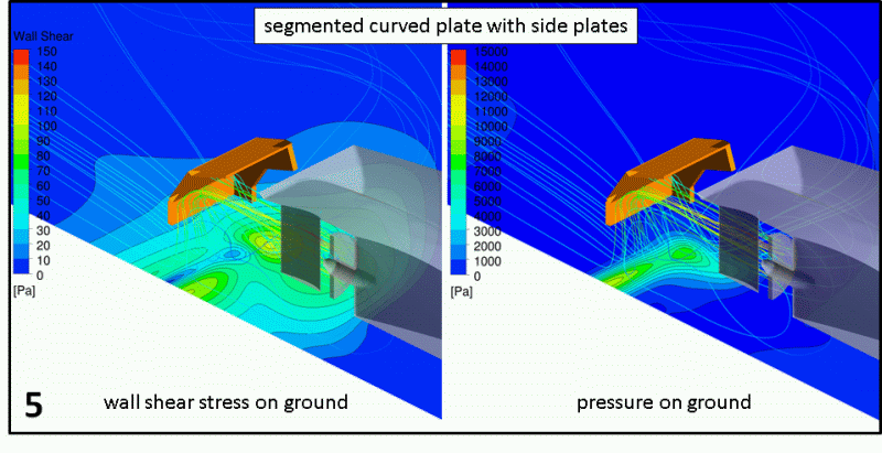
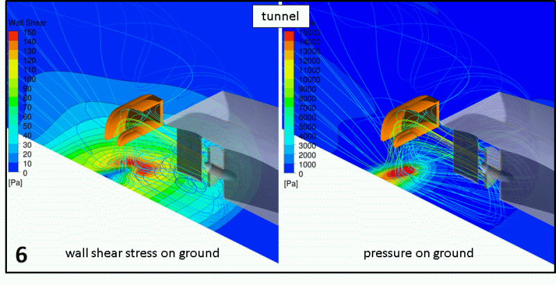
Comparison of Different Deflections – Preliminary Study
The calculations showed that a side plate is required for effective wash deflection. Through this, the spreading of the wash to the side is significantly reduced. Without a side plate, the required wall shear stress of τ = 120 Pa is not reached. Flow permeable gaps in the deflector should be avoided, as these can substantially reduce the effect of the deflection. The images to the left show the resulting values in dependence of the selected geometry variant (figures 1-6). The closed tunnel variant (figure 6) was the most effective and was selected by the client for optimisation.
Optimization of the Tunnel Variant
For the geometric optimisation of the tunnel, a parametric model was developed for the CAE program “CAESES”. The width of the entry area was set to 1.30 m. In this way, function is guaranteed even with slight rudder deflections. Through the dependency of the geometry on defined parameters, it could be changed fully automatically for optimisation. The vertical position of the upper edge of the tunnel entrance, the height of the entrance area, the length of the tunnel, the ratio of entry area to exit area and the ratio of length-to-width of the exit area were optimised using parametric variation in regard to the resulting bottom surface with a wall shear stress of τ > 120 Pa.
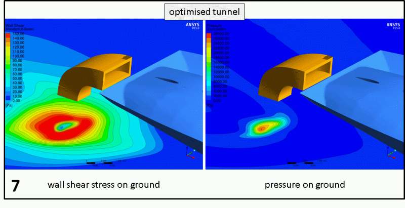
Results of the Optimization
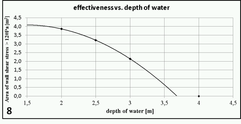
The top of the tunnel is located just below the surface of the water. To prevent the deflected wash from flowing over, the area between the ship and deflection device should be covered at the surface of the water. The breadth of the water bottom area experiencing a wall shear stress of τ > 120 Pa is about 2.5 m, the length is about 2 m. The wall shear stress and the pressure at the water bottom which are generated by the optimum tunnel variant is shown in figure 7. To demonstrate the effectiveness of the optimised tunnel geometry at different water depths, additional calculations at h = 2, 3 and 4 m were performed. The results show a moderate decrease in the effectiveness depending on the water depth. At 4 m water depth 120 Pa wall shear stress is no longer achieved (see graph in figure 8).
Evaluation of the Results
Because of the applied simplifications (fixed water surface, quasi-static calculations, actuator disc, no change in the ground topology) the results may only be qualitative. The pressure on the water bottom corresponds to 28.000 Pa (N/m^2) at a depth of h = 2.5 m. Such pressure should lead to a deformation of mud at the water bottom (washed out cavity) which will again significantly increase the flushing effect.
Comparison of Theory (SVA Simulations) and Practice (Trial Run, see below)
The optimisation of the device was carried out at a low system speed, because the self propulsion point was achieved in the calculations with PMotor = 2/3 PMotor max below 5 km/h. However, the device appears to produce a significantly lower resistance in reality. This suggests that the specification of a “fixed” water surface – despite a plate between tunnel entrance and ship – is not optimal under these circumstances. In operation, the device would clearly be washed over. To reduce the speed, the propeller wash is to be restricted in the future through additional lateral plates.
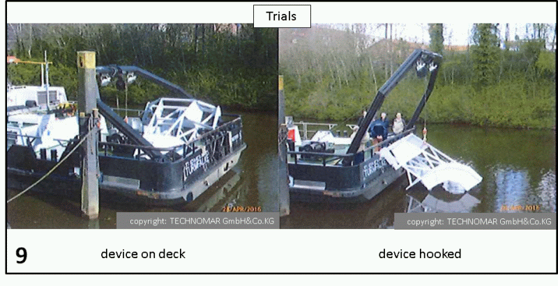
Real-World Implementation of the Wash Deflector
All following contents shown were edited by the company “TECHNOMAR GmbH & Co. KG” and provided to SVA through the Special Unit for Mechanical Engineering (FMM) of the Waterways and Shipping Office Minden from the sea trial protocol.
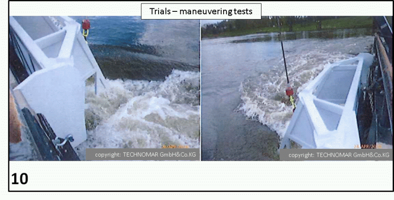
Manoeuvring Behaviour
The ship carries out rudder manoeuvres reliably. Also, no problems arise when reversing. The device reduces the boat speed under full load from 15 km/h to 12 km/h. The skipper states: “A safe manoeuvring is possible. There are no restrictions.”
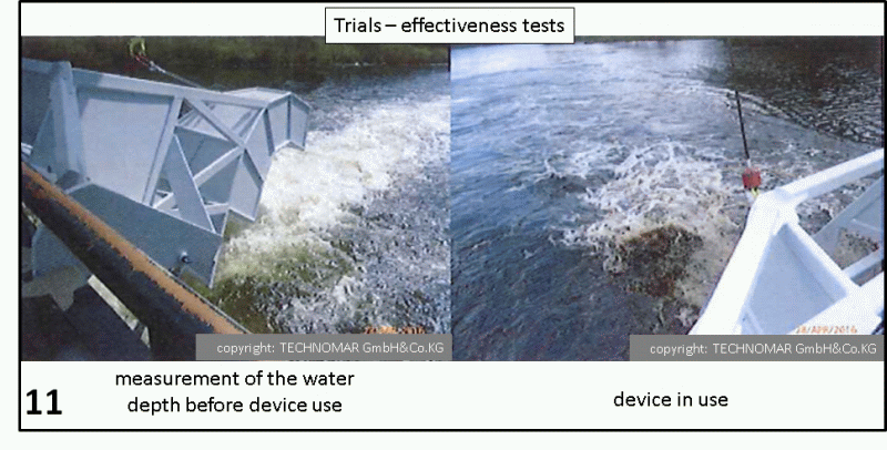
Reviewing the Effectiveness
The provided test course has been driven through and the water depths read. The water depth is 2.4 m on average. Then, a distance of 400 to 500 m is covered in a total of 3 runs with steps of different speeds. Through the flushing process the whirling water came to the surface and was deep black with sediments. After the 3rd passage gas bubbles (fermentation gases) were shown on the surface. The experiment was ended and the device taken out of the water. The test course was driven again and the water depth determined. It was now measured at around 2.80 m. The waterway course was deepened in this experiment by about 40 cm. The thrust vectoring device must now be tested in further experiments on the effectiveness of the flushing. This is carried out and documented by the WSA-Meppen. All participants believe that the device is an improvement in controlling the silt problem on the Ems River.
Courtesy of:
Fachstelle Maschinenwesen Mitte
at Minden Waterways and Shipping Office
Am Hohen Ufer 1-3
32425 Minden
Author: Dipl.-Ing. E. Schomburg