Sensors – Propeller Induced Pressure Fluctuations and Noise Spectra

Sensorik_Dummymodell_besser_small

Sensorik_Hydrofonkasten_small

Sensorik_Körperschallmessungen_small

The specification for a propeller design generally includes limits for the pressure fluctuations induced by the propeller. Moreover, acoustic limits are specified in special ships (naval and research vessels and yachts). Cavitation phenomena at propellers or appendages mainly lead to a significant increase in the amplitudes of the vibrations. Therefore pressure fluctuation, vibration and sound measurements are performed in conjunction with cavitation. In the cavitation tunnel, pressure sensors and hydrophones are placed in the stern area above the propeller or at positions of interest on the hull.

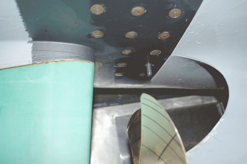
The pressure pulses induced by the propeller are measured with absolute pressure sensors. Typically, an array of sensors, 11 to 16, above the propeller is arranged.

If evidence of higher frequency levels at the hull is of interest, hydrophones are arranged in close range of the model propeller in the outer skin of the model. To determine the noise spectra induced by the propeller, hydrophones are placed on the windows or directly inside the test section of the cavitation tunnel.

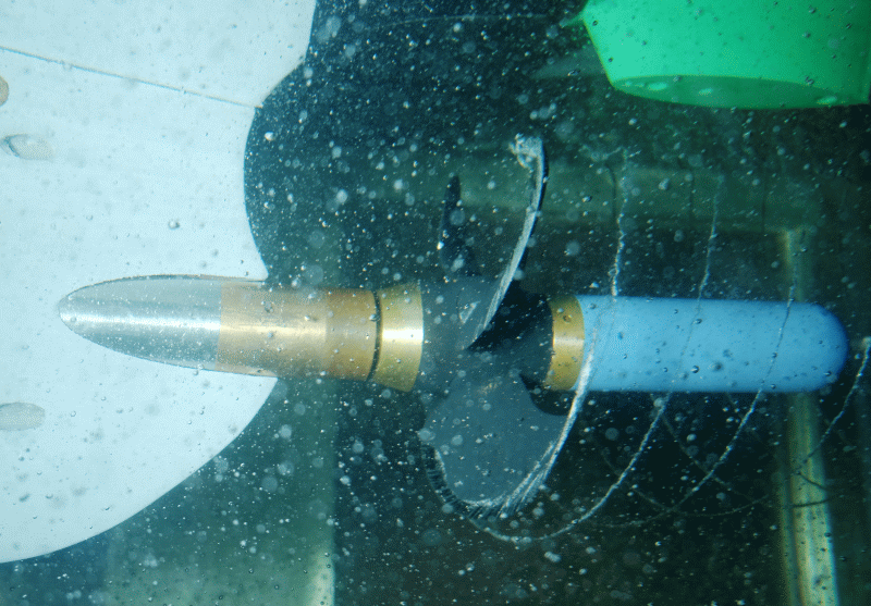
For the analysis and comparison of acoustically optimised propellers, direct measurement of vibrations is carried out on the propeller. A high frequency acoustic emission sensor is installed with pre-amplifier and transmitter in a special hub cap. The sampling rate is 44100 Hz.