
The frictional resistance of a one-sided wetted flat plate is well known from semi-empirical investigations. There are several formulas for laminar and turbulent flow, developed by e.g. Blasius, Prandtl, Schönherr, Schlichting/Gersten, etc. For Schlichting/Gersten also the roughness of the surface is included, but when dealing with complex surface structures a mere roughness consideration is not enough.
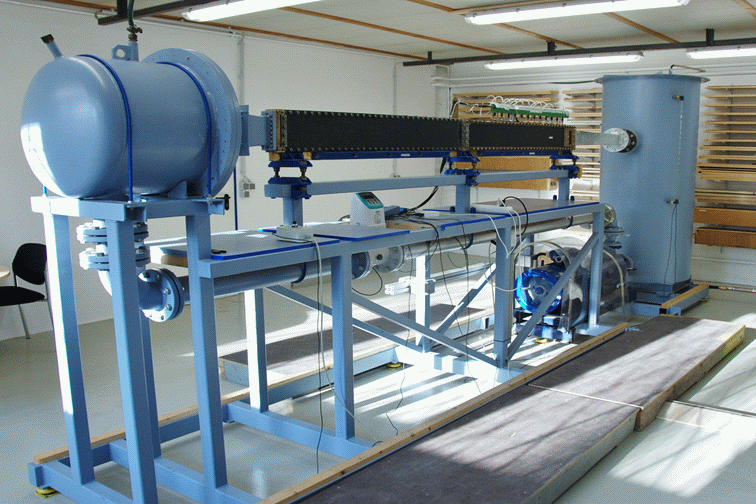
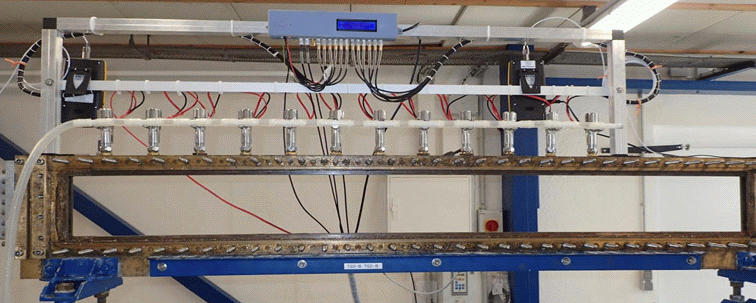
In this case, measurements as with SVAtech’s friction tunnel are still meaningful for providing reliable results in an easy way. Put simply, the friction tunnel is a small water circuit tank in which plates with the coating to be investigated can be installed. Therefore two of these plates form a narrow rectangular channel for which the wall shear stress inside can be derived from the pressure loss between several observation points. In SVAtech’s friction tunnel 12 equidistant positions over the length of the test plates are used for measuring the pressure drop. Finally, the friction coefficient is obtained by dividing the wall shear stress by the dynamic pressure.
The friction tunnel was developed in 1992 at the Research Institute for Hydraulic Engineering and Shipbuilding (Versuchsanstalt für Wasserbau und Schiffbau) in Berlin and was property of the Technical University from Berlin for a long time until in 2004 SVA bought it. To reach the high accuracy demands of the customers several modifications were necessary. The test section was extended to 12 pressure sensors and a venting valve for each pressure sensor to ensure that no air bubbles are trapped inside the circuit. A magnetic inductive flow meter helps determining the water velocity in the test section. There is a choice of two different flow meters (one covering the small and one the high water speed ranges). Furthermore, 2 temperature sensors were installed to determine the water properties like density and viscosity. A microprocessor automatically runs the engine control of the pump and conducts the calculation of the fitted pressure gradient and friction coefficient. The data is transferred to a computer where the final evaluation is done.
The test procedure is fully automated in such a way that the whole speed range from 1 m/s up to 18 m/s (or respectively log(Re) = 5.4 up to 6.7) is measured in 26 steps three times. For each step there is a waiting time of 60 s for the stabilization of the flow and finally 15 s of measurement time. In the end the mean value curve of all three runs is calculated.
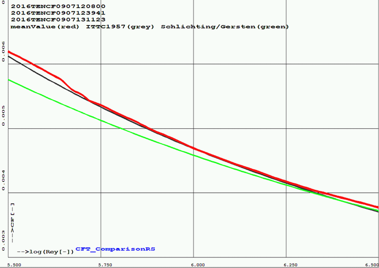
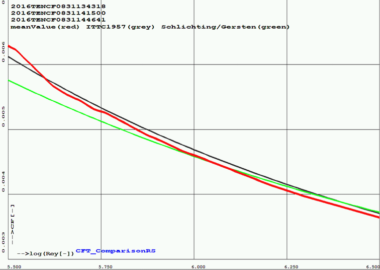
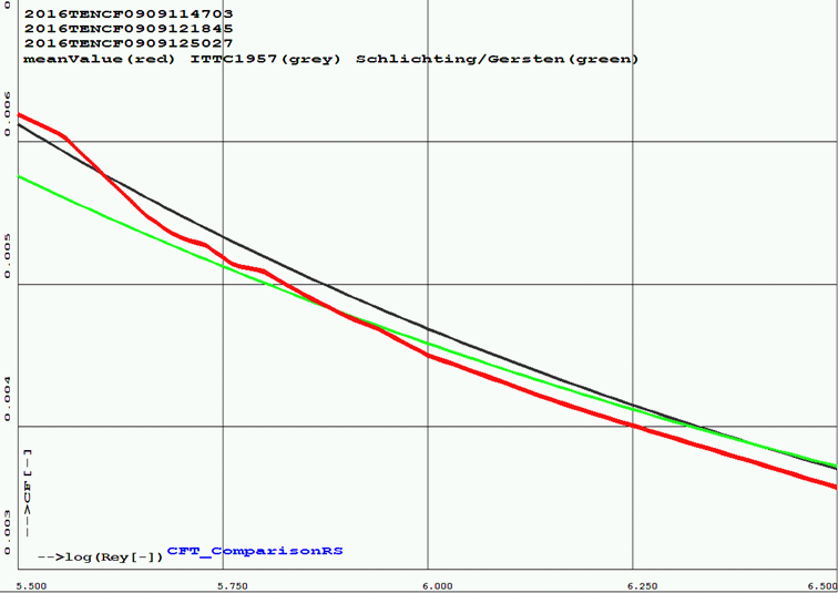
The usual way to present the results of friction measurements is in dependency of the Reynolds number. The challenge is to make the channel flow comparable with a flow around a body as for ship applications. The solution is to determine experimentally the reference length for the calculation of the Reynolds number in such a way that it equals a flow around a body. With the resulting reference length (which is almost the channel perimeter) a good accordance with the ITTC’57 curve is reached for technically smooth plates.
For textures a presentation over s+ can be more meaningful than the Reynolds number. The s+ value is the dimensionless characteristic length for one structure element, e.g. for riblet structures it is the distance of two riblets.
Different measurements were carried out. Good results were achieved with the former anti-fouling spray “Biotard”. For a wide range of Reynolds numbers the friction coefficient is slightly lower than that of the smooth plate. A bigger effect is visible when using riblets which – in a defined s+ range – can cause a significant reduction of the friction. During the investigations of riblet structures the idea came up to test “simple” riblets made by hand with sandpaper and a belt grind. The resulting structure is similar to the perfect riblet structure. The maximum friction reduction is not as big as for the perfect riblets but the Reynolds number range is wider for which the friction is lower than that of a smooth plate.
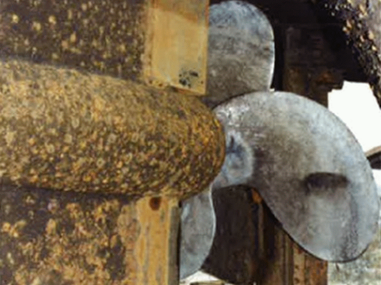
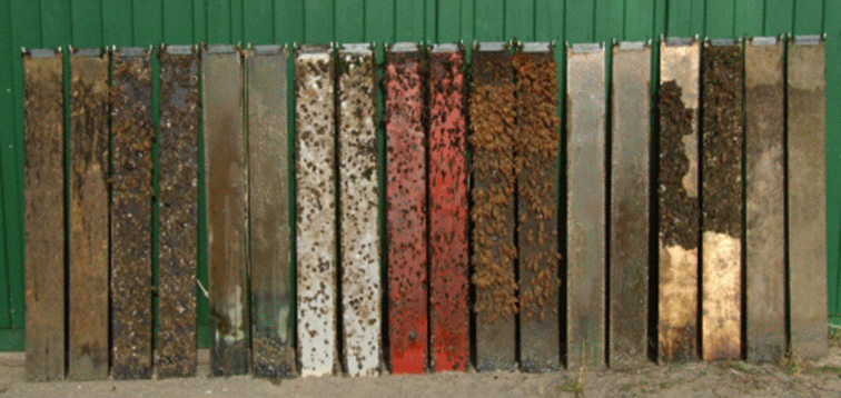
But it must not be forgotten that not only the “fresh” coating has to be investigated. It is also important to test the long term qualification after several months of operation. SVAtech simulates this in cooperation with the Laboratory LimnoMar where the test plates are exposed to the North Sea for a certain period of time. After this time the plates are tested again in the friction tunnel.
In summary, the friction tunnel provides friction characteristics of different coatings and textures in an easy and cheap way. The real surface and not only a model of it can be measured over a wide range of Reynolds number. A quick answer regarding the drag reduction and hence fuel savings can be given. The measurements are applicable for a wide field not only in the shipbuilding industry but also for the aerospace or automotive industry.
Author: M. Sc. Rhena Klose, Schiffbau-Versuchsanstalt Potsdam GmbH
The full text can be found in:
R. Klose, R. Schulze: Friction Measurements of Different Coatings in a Friction Tunnel, Proceedings 2nd Hull Performance & Insight Conference, 2017