Main Parameter |
H29 | H39 | |
| Propeller thrust | T<max [N] | 400 | 1000 |
| Propeller torque | Qmax [Nm] | 15 | 55 |
| Propeller R.P.M. | nmax [s-1] | 60 | 60 |
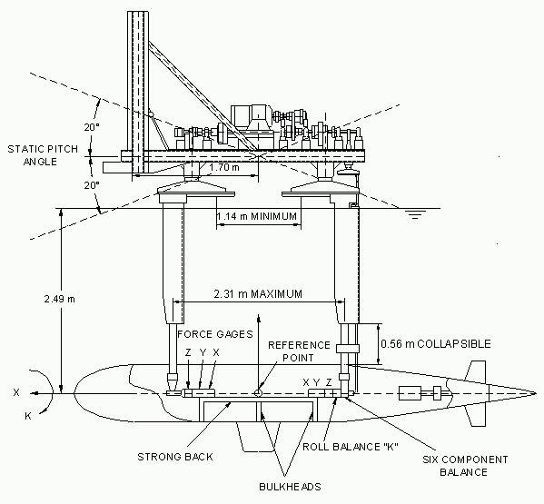
| Max. Propeller Shaft Inclination | [°] | 30 | 30 |
Main Parameter |
R25 | R31 | R73 | R40 | |
| Propeller Thrust | Tmax [N] | 100 | 250 | 600 | 150 |
| Propeller torque | Qmax [Nm] | 4 | 10 | 30 | 6 |
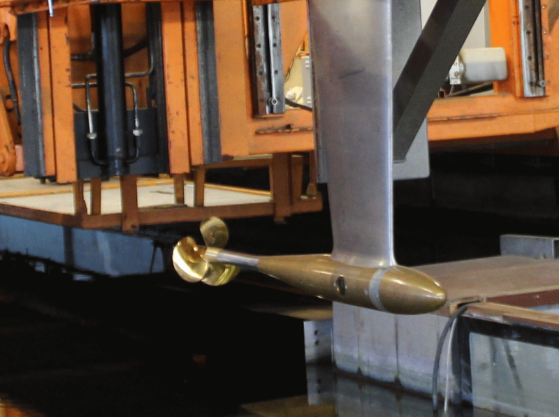
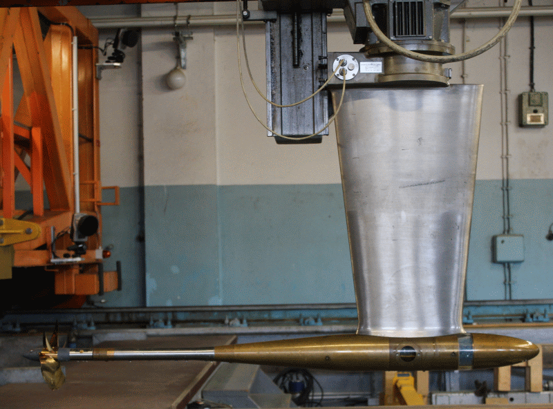
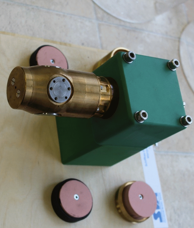
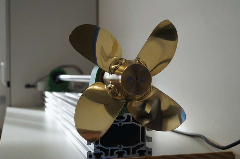
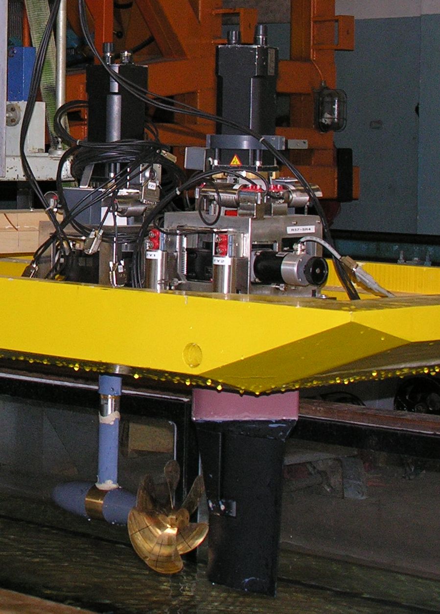
For propeller open water tests in the towing tank the following dynamometer types are mainly used: H29 and H39 from Kempf & Remmers. Both dynamometers measure the thrust and torque of the propeller. On both devices, a measuring balance for the thrust nozzle can also be mounted. The H39 can be equipped with a shaft which permits the measurement of the lateral forces of the propeller.
The dynamometers are capable for experiments with shaft inclination.
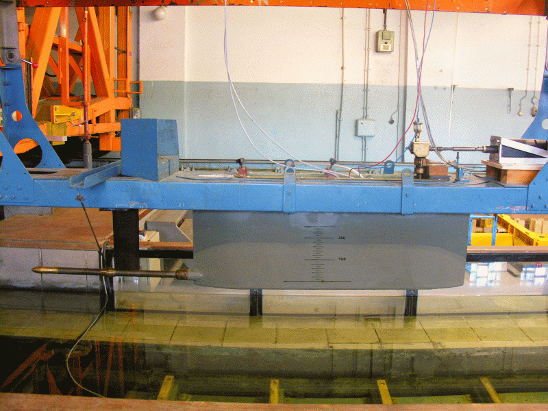
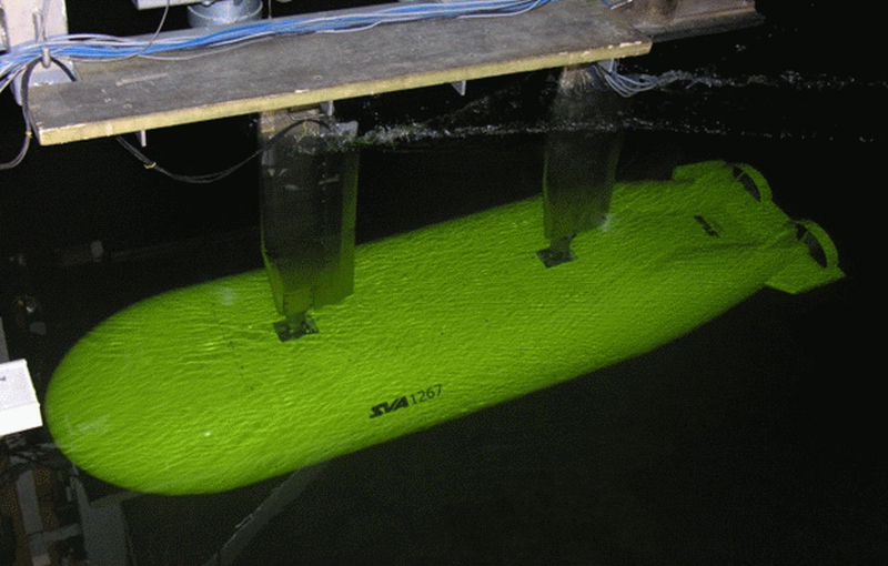
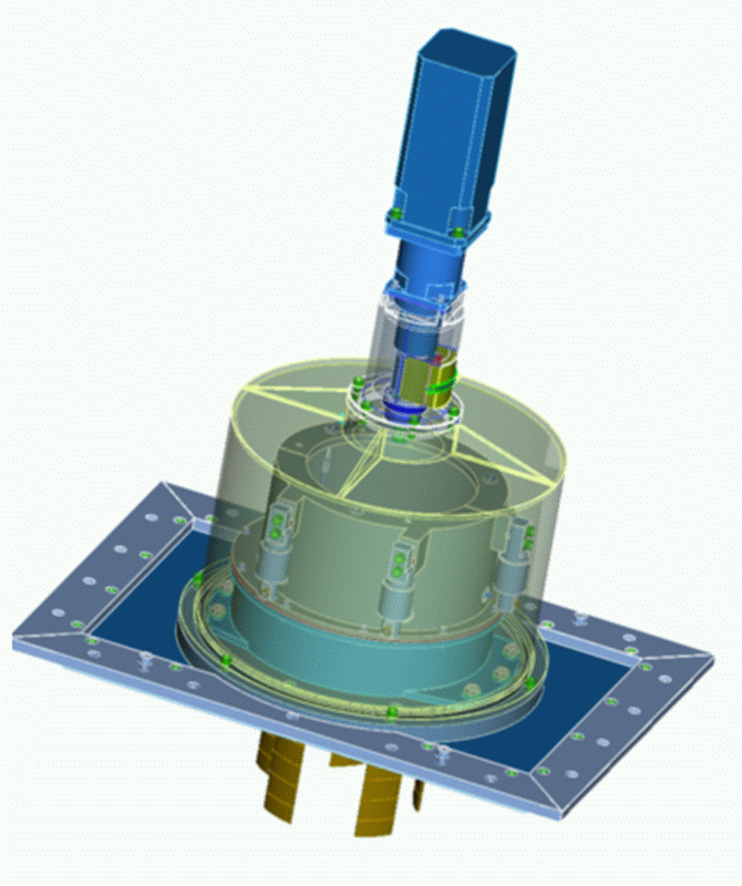
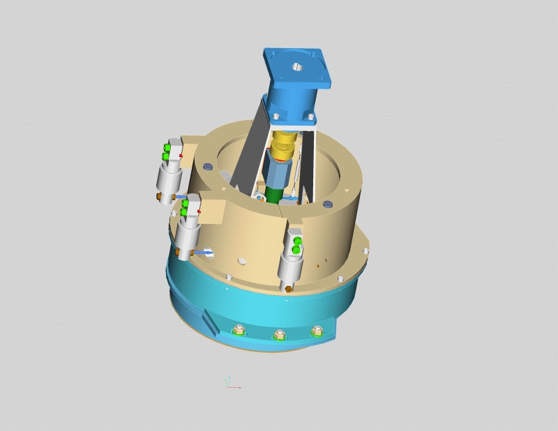
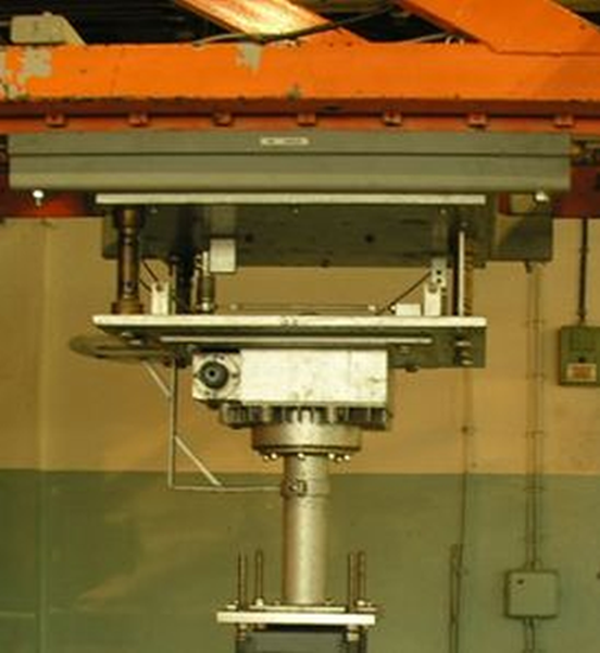
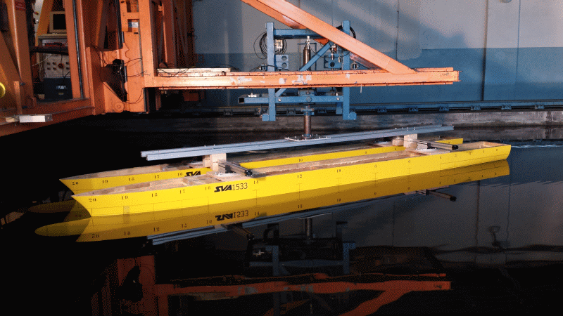
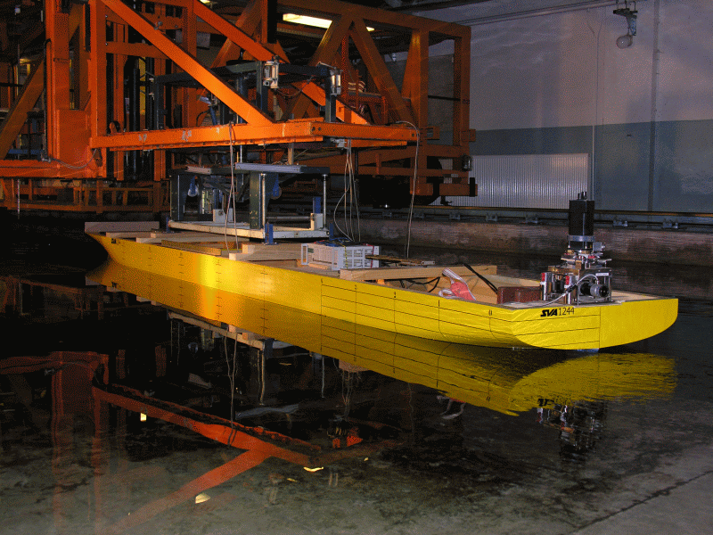
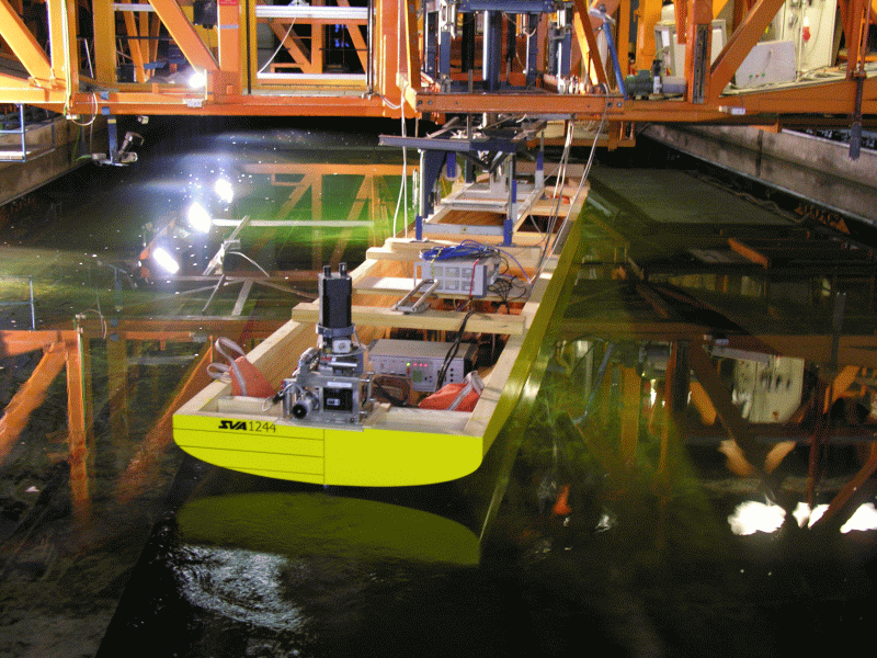
Open Water Carriages FK1, FK4
The open water carriages FK1 and FK4 offer the possibility to perform tests with internal propulsion dynamometers for ship models. Custom dynamometers from Kempf and Remmers are used for the measurement range and for the FK4 carriage, the counter rotating dynamometer R40 from Kempf & Remmers is used. A measurement balance for nozzles can also be mounted on both devices.